HMT101ATA-C
LCD Module User Manual
Prepared by:
Checked by:
Approved by:
YUrj
Date: 2019-08-06
Date:
Date:
Rev. Descriptions
Release Date
0.1
- Preliminary release
2019-08-06
URL: www.topwaydisplay.com
Document Name: HMT101ATA-C
Page: 1 of 10

TOPWAY
LCD Module User Manual
HMT101ATA-C
Table of Content
1. Basic Specification ........................................................................................................................... 3
1.1
General Specification ........................................................................................................... 3
1.2
Block Diagram ...................................................................................................................... 3
1.3
Terminal Function ................................................................................................................. 4
1.3.1
UART Interface Terminal (K1) ...................................................................................... 4
1.3.2
USB Interface Terminal (K2) ......................................................................................... 4
2. Absolute Maximum Ratings ............................................................................................................. 5
3. Electrical Characteristics ................................................................................................................. 5
3.1
DC Characteristics ................................................................................................................ 5
4. Function Specifications ................................................................................................................... 6
4.1
Basic Operation Function Descriptions ................................................................................ 6
4.2
Memory Space Allocation ..................................................................................................... 6
4.3
Quick Start Guide ................................................................................................................. 7
5. Command Descriptions .................................................................................................................... 7
6. Optical Characteristics ..................................................................................................................... 8
7. Touch panel Design Precautions .................................................................................................. 10
8. Precautions of using LCD Modules .............................................................................................. 10
URL: www.topwaydisplay.com
Document Name: HMT101ATA-C
Page: 2 of 10
TOPWAY
LCD Module User Manual
HMT101ATA-C
1. Basic Specification
TOPWAY HMT101ATA-C is a Smart TFT Module with 32bit MCU on board. Its graphics engine
provides numbers of outstanding features. It supports TOPWAY TML for preload and pre-design
display interface that simplify the host operation and development time. Suitable for industry control,
instrumentation, medical electronics, power electric equipment applications.
1.1 General Specification
Screen Size(Diagonal) :
10.1”
Resolution :
1024(RGB) x 600
Color Depth :
65k color (16bit)
Pixel Configuration :
RGB Stripe
Display Mode :
Transmissive / Normal Black
Viewing Direction :
6H (*1) (gray-scale inverse)
12H (*2)
Outline Dimension :
251.0 x 140x 19.1 (mm)
(see attached drawing for details)
Active Area :
222.72 x 125.28(mm)
Backlight :
LED
Surface Treatment :
Anti-Glare Treatment
Touch Panel:
Resistive Touch Panel
Operating Temperature :
-20 ~ +70°C
Storage Temperature :
-30 ~ +80°C
Note:
*1. For saturated color display content (eg. pure-red, pure-green, pure-blue, or pure-colors-combinations).
*2. For “color scales” display content.
*3. Color tone may slightly change by Temperature and Driving Condition.
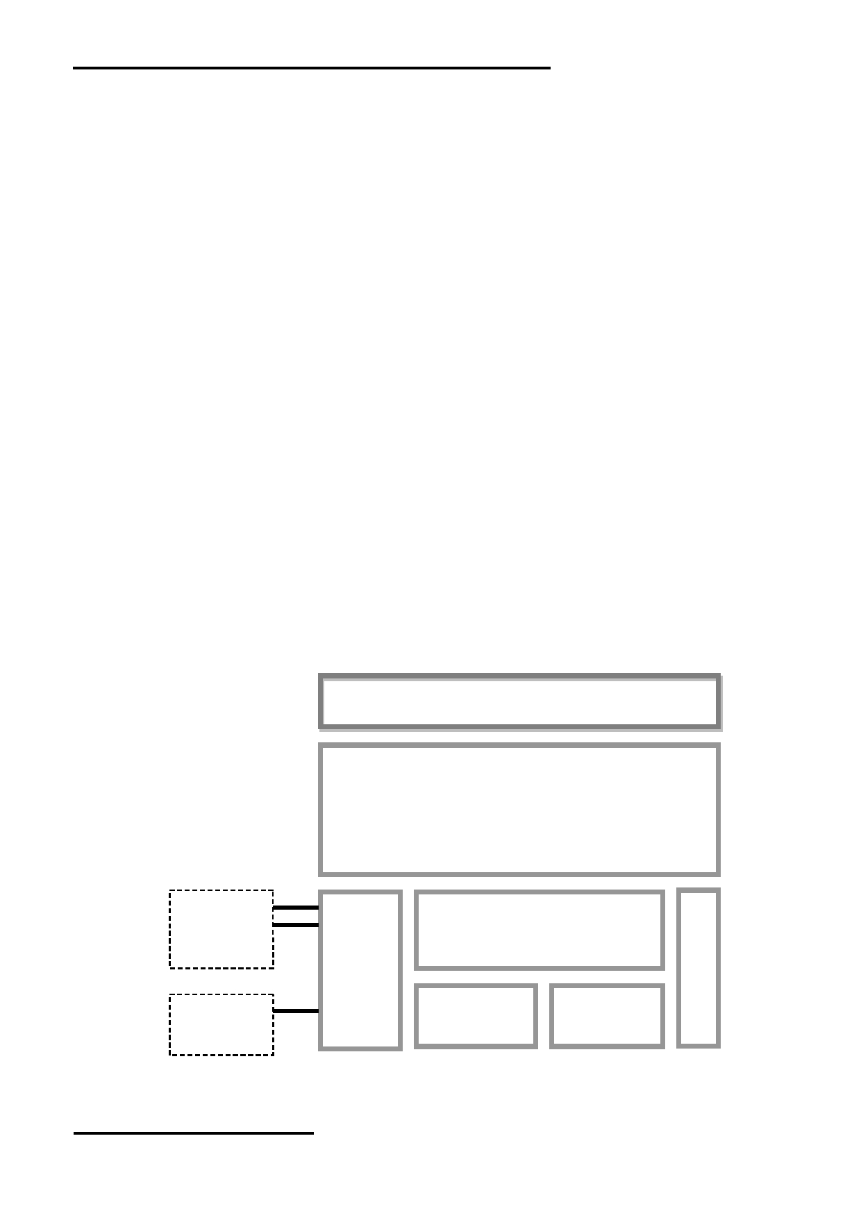
1.2 Block Diagram
Resistive Touch Panel
10.1” TFT
1024 x 600 pixels
K1
RTS(BUSY)
TX, RX
Display Function Controller
VDD,GND
K2
D+, D-,ID
Flash
Memory
RAM
VUSB, GND
URL: www.topwaydisplay.com
Document Name: HMT101ATA-C
Page: 3 of 10
TOPWAY
LCD Module User Manual
HMT101ATA-C
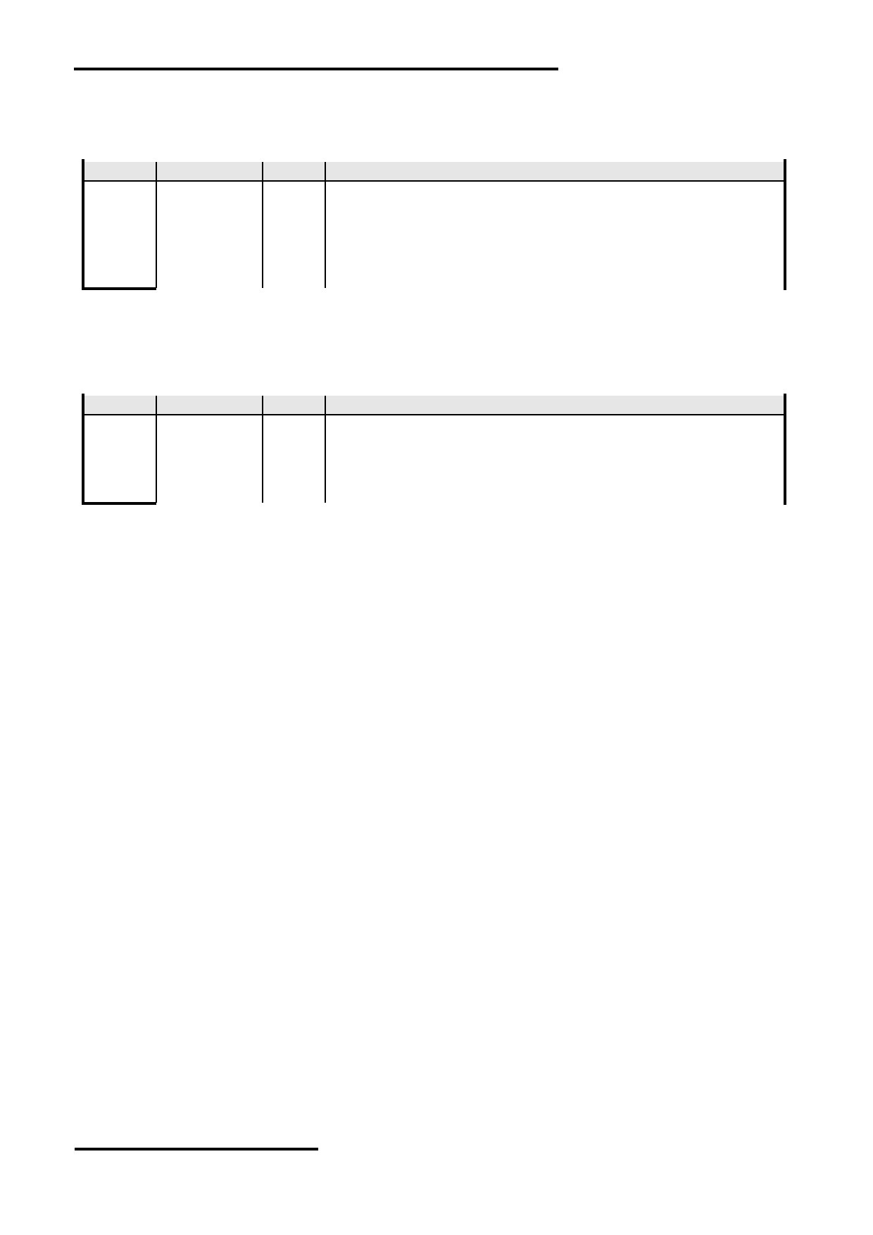
1.3 Terminal Function
1.3.1 UART Interface Terminal (K1)
Pin No.
Pin Name
I/O Descriptions
1,2
VDD
P
Power supply
3
RTS(BUSY)
O
Request To Send (function as busy BUSY signal)
1 : Busy ; 0 : No busy
4
TX
O
Data output
5,6
RX
I
Data Input
7,8
GND
P
Ground, (0V)
Note.
*1. User data and commands transfer through this terminal
*2. HW hand shake is suggested
1.3.2 USB Interface Terminal (K2)
Pin No.
Pin Name
I/O Descriptions
1
VUSB
P
Power supply
2
D-
I/O
USB DATA negative signal
3
D+
I/O
USB DATA positive signal
4
ID
I
USB_ID,1:Client,0:HOST
5
GND
P
Ground, (0V)
Note.
*1. TML files and image files preload through this terminal.
*2. Do NOT connect USB terminal ,while VDD(K1) is present.
URL: www.topwaydisplay.com
Document Name: HMT101ATA-C
Page: 4 of 10
TOPWAY
LCD Module User Manual
HMT101ATA-C
2. Absolute Maximum Ratings
Items
Symbol
Min.
Max.
Unit
Condition
Power Supply voltage
V DD
-0.3
28
V
Operating Temperature
T OP
-20
70
C
No Condensation
Storage Temperature
T ST
-30
80
C
No Condensation
Note:
*1. This rating applies to all parts of the module and should not be exceeded.
*2. The operating temperature only guarantees operation of the circuit. The contrast, response speed,
and the other specification related to electro-optical display quality is determined at the room temperature, T OP =25 ℃
*3. Ambient temperature when the backlight is lit (reference value)
*4. Any Stresses exceeding the Absolute Maximum Ratings may cause substantial damage to the device. Functional
operation of this device at other conditions beyond those listed in the specification is not implied and prolonged
exposure to extreme conditions may affect device reliability.
3. Electrical Characteristics
3.1 DC Characteristics
VDD=12V,GND=0V, T OP =25 C
Items
Symbol
MIN.
TYP.
MAX.
Unit
Applicable Pin
Operating Voltage
V DD
11
12.0
26
V
VDD
RxD Input MARK(1)
V RxDM
-3.0
-
-15.0
V
Rx
RxD Input SPACE(0)
V RXDS
+3.0
-
+15.0
V
Rx
TxD Output MARK(1)
V TXDM
-3.0
-
-15.0
V
Tx
TxD Output SPACE(0)
V TXDS
+3.0
-
+15.0
V
Tx
RTS Output High
V TXDH
-3.0
-
-15.0
V
RTS(BUSY)
RTS Output Low
V TXDL
+3.0
-
+15.0
V
RTS(BUSY)
Operating Current
I DD
-
350
-
mA
VDD (*1)
Battery Supply Current
I BAT
-
0.6
-
uA
Note.
*1. Normal display condition and no usb connect.
URL: www.topwaydisplay.com
Document Name: HMT101ATA-C
Page: 5 of 10
TOPWAY
LCD Module User Manual
HMT101ATA-C
4. Function Specifications
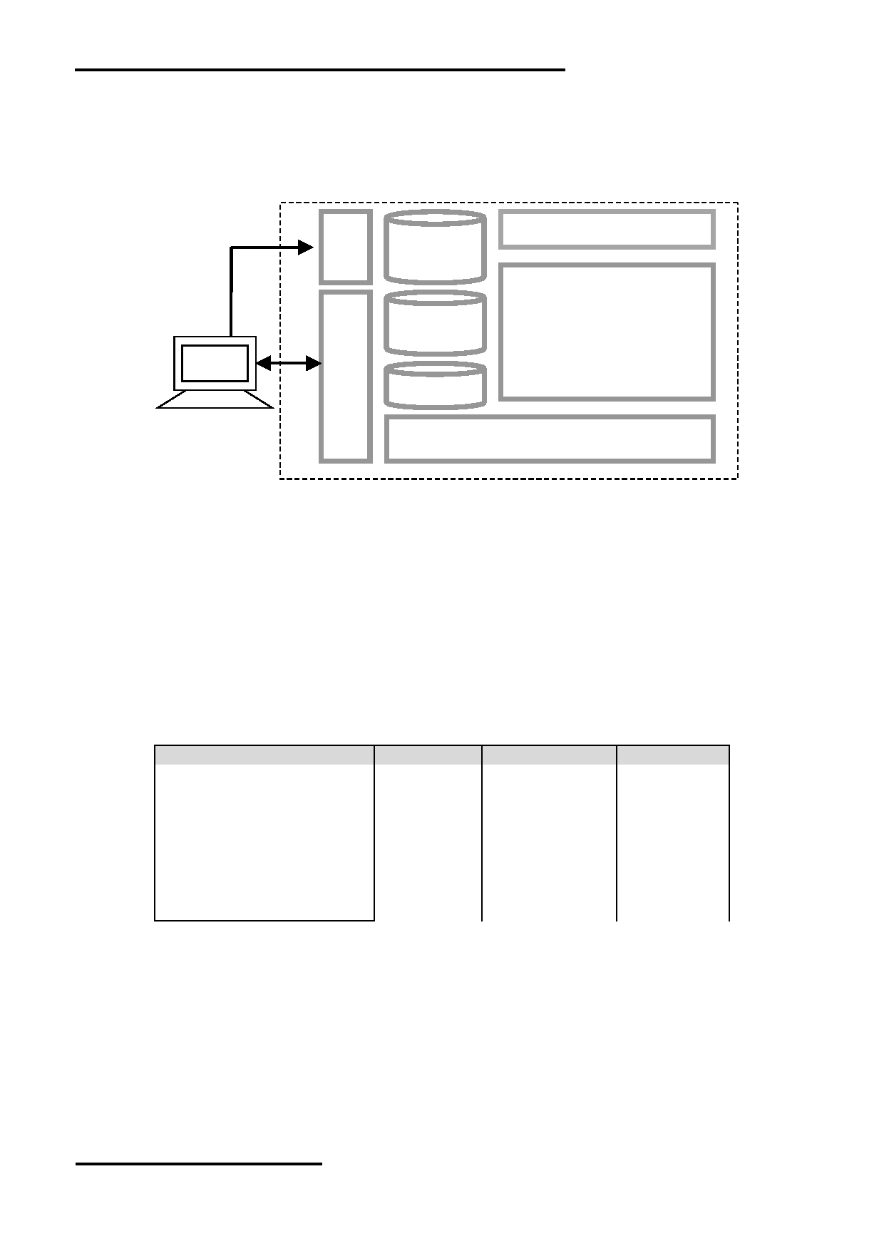
4.1 Basic Operation Function Descriptions
HMT101ATA-C
touch panel
TML files
Picture files
ICONS files
Custom
Memories
TFT Display
HOST
PC
VP variables
Control and Draw Engine
- TML files, Picture files, ICON files are stored inside FLASH memory area.
They are preloaded to HMT101ATA-C for stand alone interface use.
- Those files are preloaded via USB interface as an USB drive.
- All the interface flow and the touch response are based on the preloaded TML files
- VP variables memory is inside RAM area,
it provides real time access via UART by the HOST or display onto the TFT by TML file.
- Custom Memories are inside FLASH memory area
It can be accessed via UART interface by the HOST.
- Control and Draw Engine executes HOST commands and response respectively
- It also reports the real time Touch Key number to the HOST
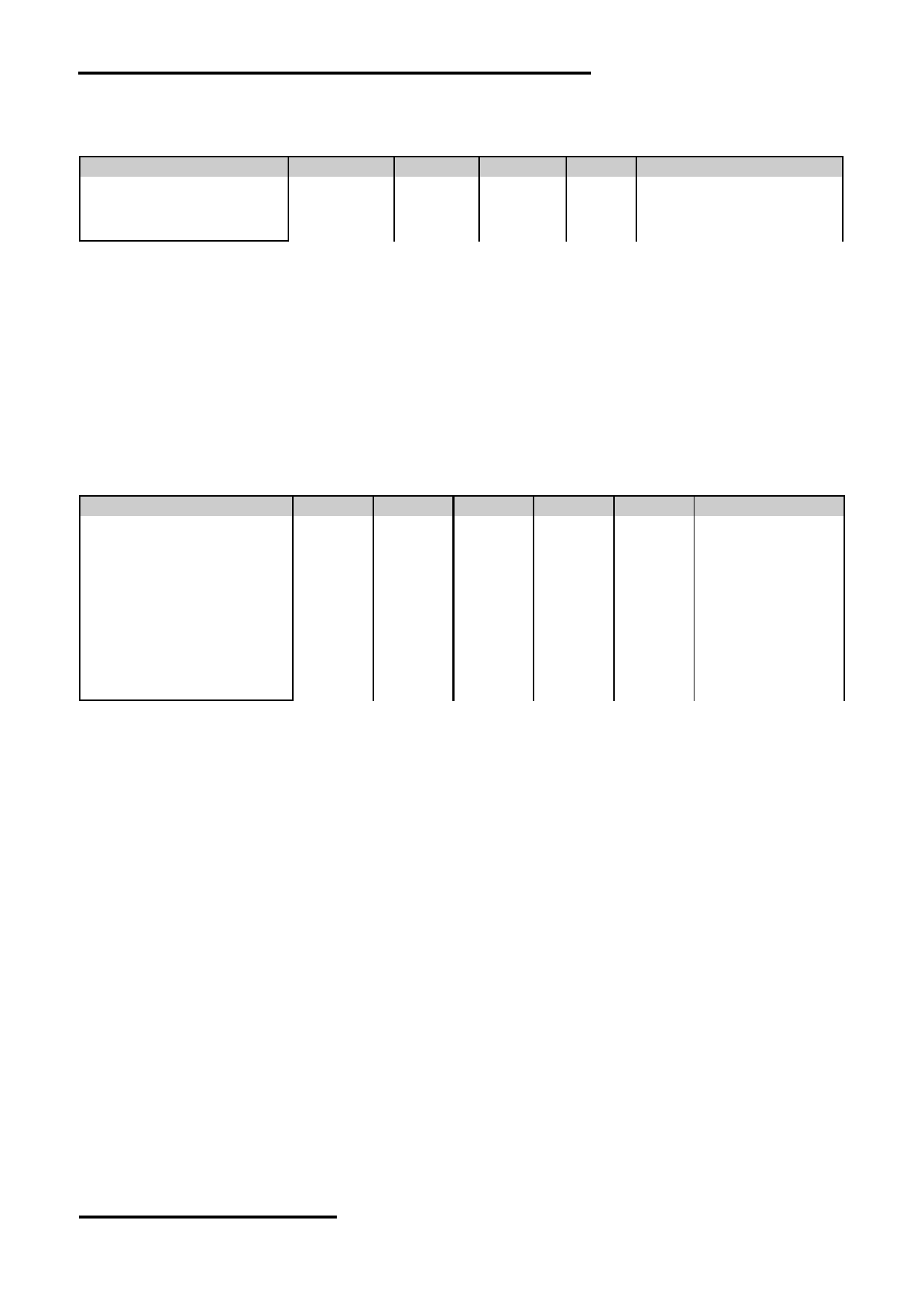
4.2 Memory Space Allocation
Function
Name
Memory sapce
Unit size
128byte string
VP_STR
128k byte
128 byte
16bit number (*1)
VP_N16
64k byte
2 byte
32bit number (*1)
VP_N32
64k byte
4 byte
64bit number (*1)
VP_N64
64k byte
8 byte
16bit Graph data array (*1)
VP_G16
128k byte
Dynamic
Bit-map data
VP_BP1
128k byte
Dynamic
Customer Flash
Cust_Flash
256k byte
1 byte
USR BIN
USR_bin
256k byte
1 byte
Note.
*1. Signed integer number
URL: www.topwaydisplay.com
Document Name: HMT101ATA-C
Page: 6 of 10
TOPWAY
LCD Module User Manual
HMT101ATA-C
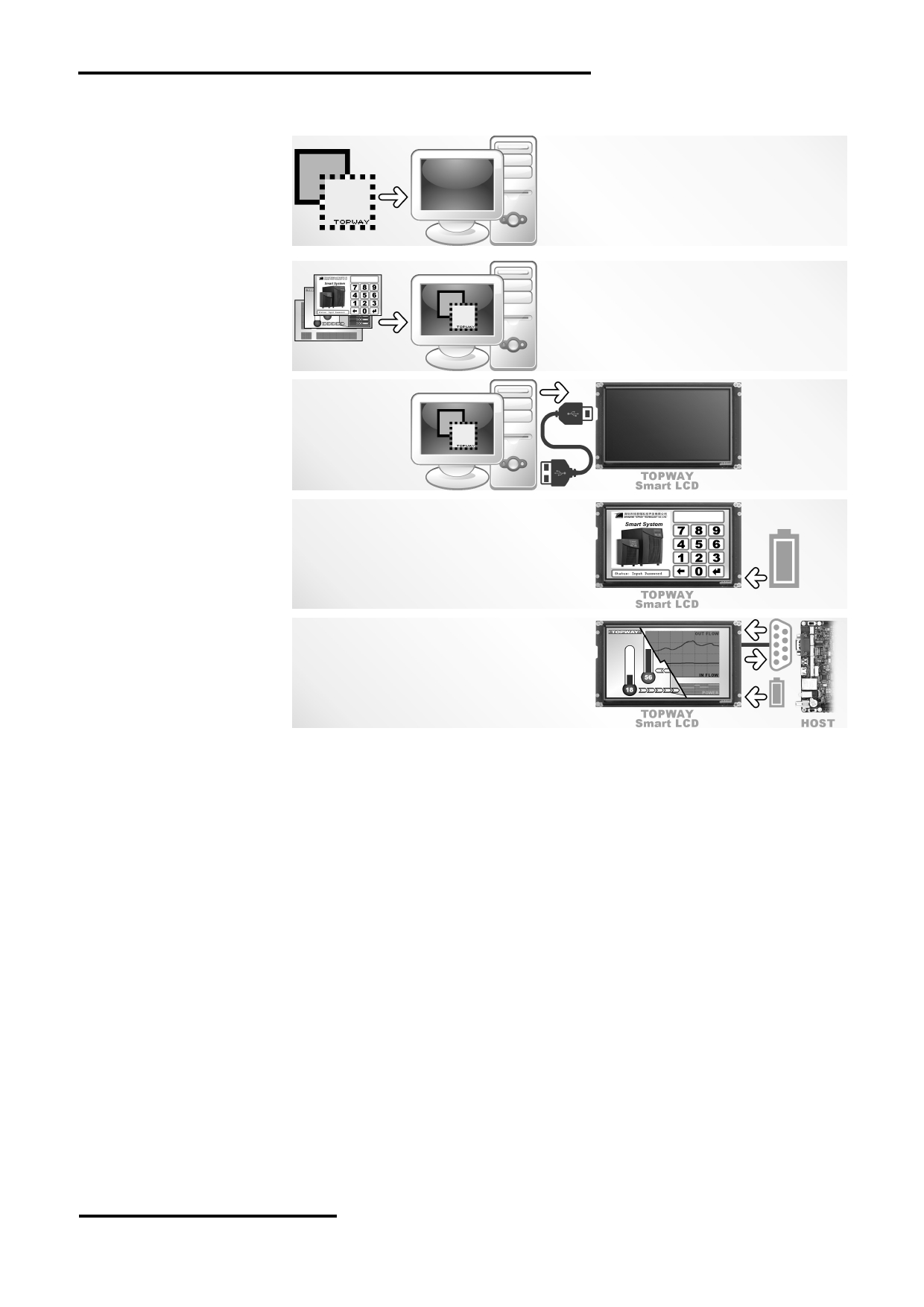
4.3 Quick Start Guide
1.
Install TOPWAY
Graphics Editor
Import
pictures
2. design UI flow
3.
Download to
Smart LCD
4. power on & d
isplay
Connect to
5.
host Show
real time
data
5. Command Descriptions
Please refer to “SMART LCD Command Manual” .
URL: www.topwaydisplay.com
Document Name: HMT101ATA-C
Page: 7 of 10
TOPWAY
LCD Module User Manual
HMT101ATA-C
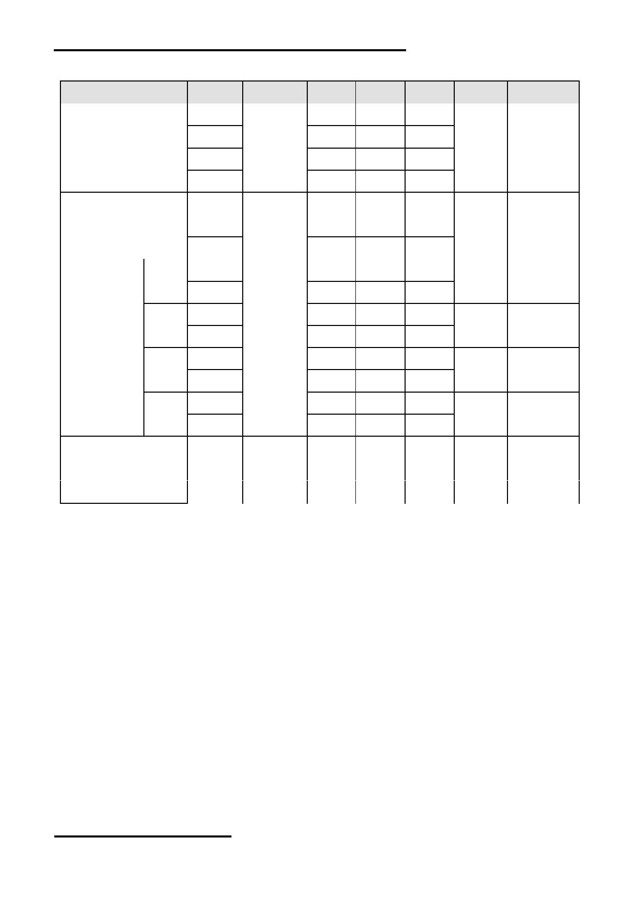
6. Optical Characteristics
Item
Symbol Condition
Min
Typ
Max
Unit
Remark
θT
65
75
-
View Angles
θB
CR ≧ 10
70
80
-
Degree Note2,3
θL
70
80
-
θR
70
80
-
Contrast Ratio
CR
θ =0 °
600
800
-
Note 3
T ON
-
7
10
Response Time
25 ℃
ms
Note 4
T OFF
-
9
18
x
0.241
0.281
0321
White
Note 1,5
y
0.260
0.300
0.340
x
0.518
0.558
0.598
Red
Note 1,5
Chromaticity
Backlight is
y
0.288
0.328
0.368
x
on
0.276
0.316
0.356
Green
Note 1,5
y
0.522
0.562
0.602
x
0.115
0.155
0.195
Blue
Note 1,5
y
0.074
0.114
0.154
Uniformity
U
70
80
-
%
Note 6
NTSC
40
50
-
%
Note 5
Luminance
L
-
300
-
cd/ ㎡ Note 7
1. The ambient temperature is 25 ℃ .
2. The test systems refer to Note 1 and Note 2.
URL: www.topwaydisplay.com
Document Name: HMT101ATA-C
Page: 8 of 10
TOPWAY
LCD Module User Manual
HMT101ATA-C
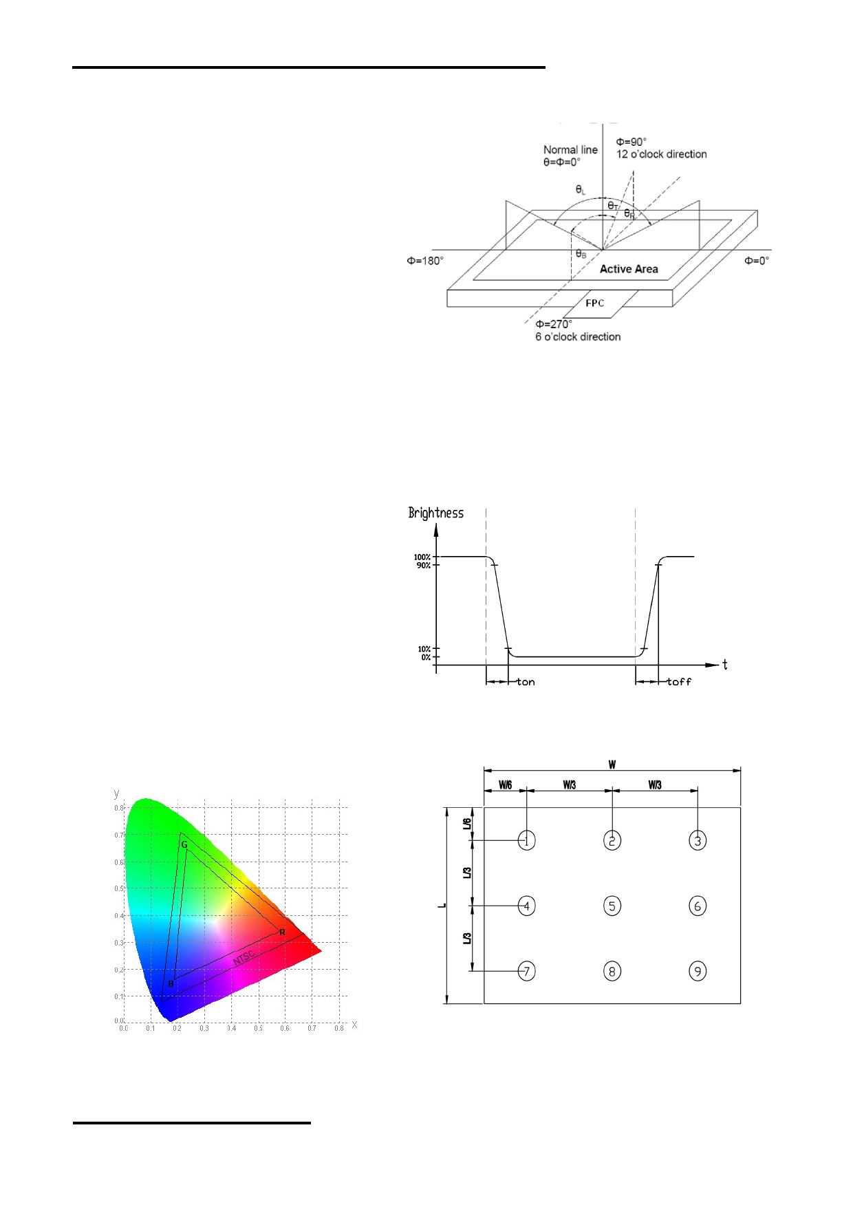
Note 1:
Note 2:
The data are measured after LEDs are turned on for 5
The definition of viewing angle:
minutes. LCM displays full white. The brightness is the
Refer to the graph below marked by θ and Ф
average value of 9 measured spots. Measurement
equipment SR-3A (1°)
Measuring condition:
- Measuring surroundings: Dark room
- Measuring temperature: Ta=25 ℃ .
- Adjust operating voltage to get optimum contrast
at the center of the display.
Note 3:
The definition of contrast ratio (Test LCM using SR-3A (1°)):
Note 4:
Luminance When LCD is at “White”
Definition of Response time. (Test LCD using BM-7A(2°)):
Contrast
state
The output signals of photo detector are measured
Ratio(CR)
=
Luminance When LCD is at “Black”
when the input signals are changed from
state
“black” to “white”(falling time)
(Contrast Ratio is measured in optimum common electrode
and from “white” to “black”(rising time), respectively.
voltage)
The response time is defined as
the time interval between the 10% and 90% of amplitudes.Refer to
figure as below.
Note 5:
Note 6:
Definition of Color of CIE1931 Coordinate and NTSC Ratio.
The luminance uniformity is calculated by using following formula.
△ Bp = Bp (Min.) / Bp (Max.)×100 (%)
Color gamut:
Bp (Max.) = Maximum brightness in 9 measured spots
Area of RGB triangle
S=
X100%
Bp (Min.) = Minimum brightness in 9 measured spots .
Area of NTSC triangle
Note 7:
Measured the luminance of white state at center point
URL: www.topwaydisplay.com
Document Name: HMT101ATA-C
Page: 9 of 10
TOPWAY
LCD Module User Manual
HMT101ATA-C
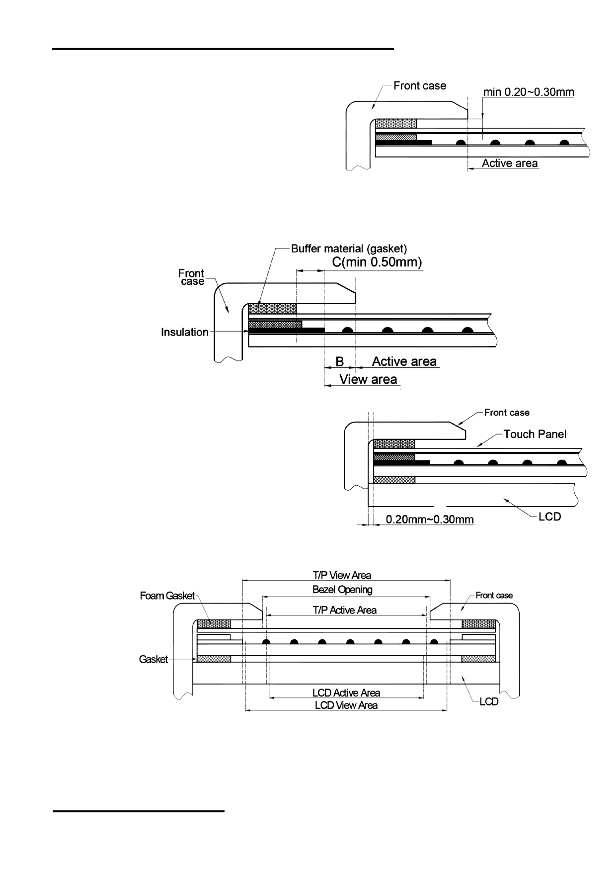
7. Touch panel Design Precautions
1. It should prevent front case touching the touch
panel Active Area (A.A.) to prevent abnormal
touch.
It should left gab (e.g. 0.2~0.3mm) in between.
2. Outer case design should take care about the area outside the A.A.
Those areas contain circuit wires which is having different thickness. Touching those areas could de-
form the ITO film. As a result case the ITO cold be damaged and shorten its lifetime.
It is suggested to protect those areas with gasket (between the front case and the touch panel).
The suggested figures are B≥0.50mm; C≥0.50mm 。
3. The front case side wall should keep space
(e.g. 0.2 ~ 0.3mm) from the touch panel.
4. In general design,
touch panel V.A. should be bigger than the LCD V.A.
and touch panel A.A. should be bigger than the LCD A.A.
8. Precautions of using LCD Modules
Please refer to "LCD-Module-Design-Handling-Precaution.pdf".
URL: www.topwaydisplay.com
Document Name: HMT101ATA-C
Page: 10 of 10