LM160160ACW-1
LCD Module User Manual
Prepared by:
Checked by:
Approved by:
Weironglin
Date: 2019-04-19
Date:
Date:
Rev. Descriptions
Release Date
0.1
Preliminary release
2011-08-19
0.2
Update 2. Absolute Maximum Ratings
2019-04-19
URL: www.topwaydisplay.com
Document Name: LM160160ACW-1-Manual-Rev0.2
Page: 1 of 12

TOPWAY
LCD Module User Manual
LM160160ACW-1
Table of Content
1. Basic Specifications ............................................................................................................... 3
1.1
Display Specifications ........................................................................................................ 3
1.2
Mechanical Specifications .................................................................................................. 3
1.3
Block Diagram ..................................................................................................................... 3
1.4
Terminal Functions ............................................................................................................. 4
2. Absolute Maximum Ratings ................................................................................................... 5
3. Electrical Characteristics ....................................................................................................... 5
3.1
DC Characteristics .............................................................................................................. 5
3.2
LED Backlight Circuit Characteristics ............................................................................... 5
3.3
AC Characteristics .............................................................................................................. 6
4. Function specifications .......................................................................................................... 7
4.1
Resetting the LCD module .................................................................................................. 7
4.2
Display Commands ............................................................................................................. 8
5. Design and Handling Precaution ......................................................................................... 12
URL: www.topwaydisplay.com
Document Name: LM160160ACW-1-Manual-Rev0.2
Page: 2 of 12
TOPWAY
LCD Module User Manual
LM160160ACW-1
1. Basic Specifications
1.1 Display Specifications
1) LCD Display Mode
: FSTN, Positive, Transflective
2) Display Color
: Display Data = “1” : Dark Gray(*1)
: Display Data = “0” : Light Gray (*2)
3) Viewing Angle
: 6H
4) Driving Method
: 1/160 duty, 1/10 bias
5) Backlight
: White LED backlight
Note:
*1. Color tone may slightly change by Temperature and Driving Condition.
*2. The Color is defined as the inactive / background color
*3. Fine Contrast adjustment function is necessary in the application design for optimal display result
1.2 Mechanical Specifications
1) Outline Dimension
: 83.8 x 76.5 x 9.6MAX (mm)
(See attached Outline Drawing for details)
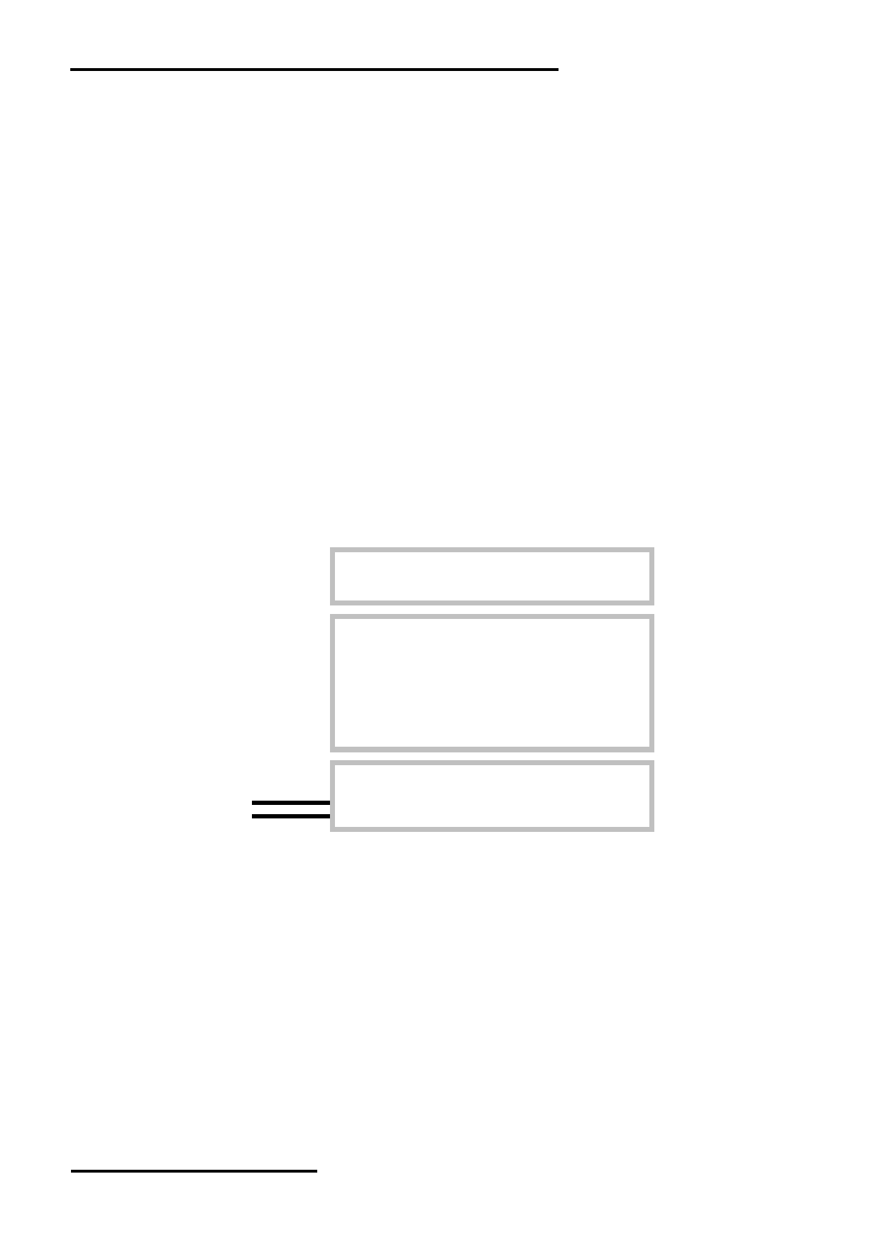
1.3 Block Diagram
BLA
BLK
Backlight Circuit
LCD Panel
160 × 160Pixels
VDD
VSS
DB0~DB7
UC1698 or equivalent
/CS0, /RST, D/C, /WR, /RD
URL: www.topwaydisplay.com
Document Name: LM160160ACW-1-Manual-Rev0.2
Page: 3 of 12
TOPWAY
LCD Module User Manual
LM160160ACW-1
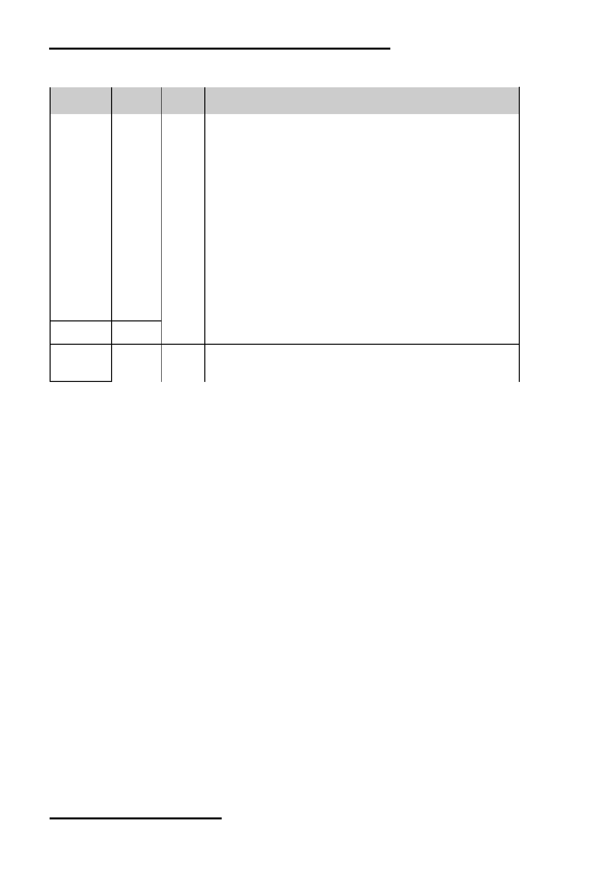
1.4 Terminal Functions
PIN
Pin No.
Name
I/O
Descriptions
1
VSS
Supply Negative power supply,0V
2
D/C
Input
Register Select
D/C = H, Transferring the Display Data
D/C = L, Transferring the Control Data
3
/WR
Input
/WR=L H, /RD=H;
Data or Instruction latch into the LCD module
4
/RD
Input
/WR=H, /RD=L;
Data or Status read form the LCD module
5
Input
Chip Select
/CS0
CS0=L, enable access to the LCD module
CS0=H, disable access to the LCD module
6
Input
Reset signal
/RST
/RST = L, Initialization is executed
/RST = H, Normal running.
7
VDD
Supply Positive power supply
8
DB0
I/O
8-bit Data bus;
:
:
Three state I/O terminal for display data or instruction data
15
when /CS=H,
DB7
DB0~DB7=High Impedance
16
BLK
Supply Negative power for LED backlight
17
NC
-
No connection, leave open
18
BLA
Supply Positive power for LED backlight
URL: www.topwaydisplay.com
Document Name: LM160160ACW-1-Manual-Rev0.2
Page: 4 of 12
TOPWAY
LCD Module User Manual
LM160160ACW-1
2. Absolute Maximum Ratings
Items
Symbol
Min.
Max.
Unit Condition
Supply Voltage
V DD
-0.3
+3.6
V
V SS = 0V
Input Voltage
V IN
-0.3
V DD +0.3
V
V SS = 0V
Operating Temperature
T OP
-40
+70
C
No Condensation
Storage Temperature
T ST
-40
+70
C
No Condensation
Cautions:
Any Stresses exceeding the Absolute Maximum Ratings may cause substantial damage to the device. Functional
operation of this device at other conditions beyond those listed in the specification is not implied and prolonged exposure
to extreme conditions may affect device reliability.
3. Electrical Characteristics
3.1 DC Characteristics
V SS =0V, V DD =3.0V, T OP =25 C
Items
Symbol
MIN.
TYP.
MAX.
Unit
Condition /
Application Pin
Operating Voltage
V DD
2.7
3.0
3.3
V
VDD
Input High Voltage
V IH
0.8xV DD
-
V DD
V
/RST, CS, D/C,
Input Low Voltage
V IL
V SS
-
0.2xV DD
V
DB0~DB7, /RD, WR
Operating Current
I DD
-
-
8.0
mA
VDD
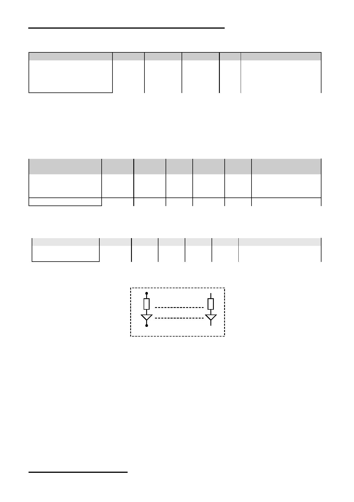
3.2 LED Backlight Circuit Characteristics
VSS=0V, If BLA =68mA, T OP =25 C
Items
Symbol
MIN.
TYP.
MAX.
Unit
Applicable Pin
Forward Voltage
Vf BLA
-
3.3
-
V
BLA
Forward Current
If BLA
-
68
80
mA
BLA
Cautions:
Exceeding the recommended driving current could cause substantial damage to the backlight and shorten its lifetime.
BLA
BLK
No. of LED = 4pcs
URL: www.topwaydisplay.com
Document Name: LM160160ACW-1-Manual-Rev0.2
Page: 5 of 12
TOPWAY
LCD Module User Manual
LM160160ACW-1
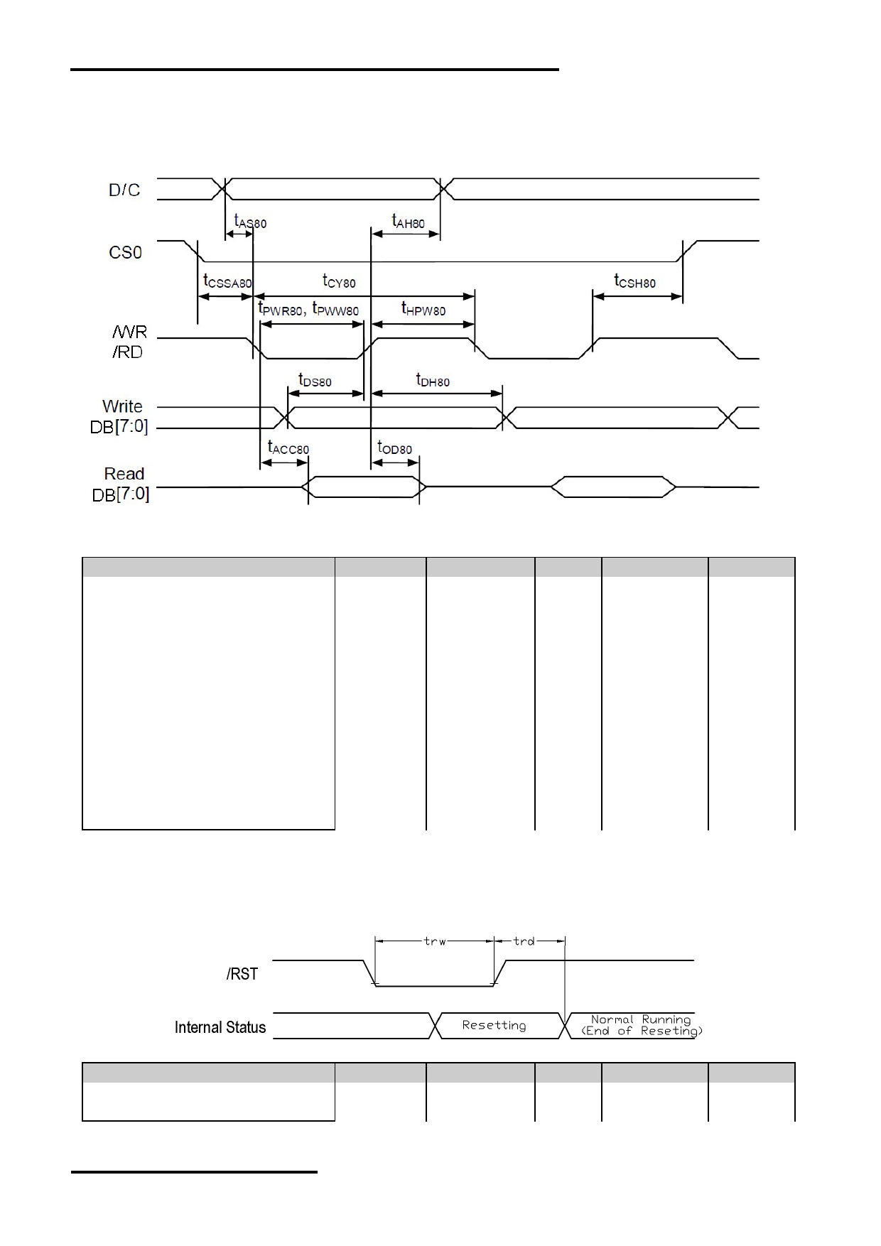
3.3 AC Characteristics
3.3.1 8080 Mode System Bus Timing
V SS =0V, V DD =3.0V, T OP =25 C
Item
Symbol
MIN.
TYP.
MAX.
Unit
Address setup time (D/C)
tas80
5
-
-
ns
Address hold time (D/C)
tah80
5
-
-
ns
System cycle time (8bit)
tcy80
145
-
-
ns
Read pulse width
tpwr80
107
-
-
ns
Write pulse width
tpww80
65
-
-
ns
High pulse width (read)
thpw80
63
-
-
ns
High pulse width (write)
thpw80
67
-
-
ns
Data setup time
tds80
38
-
-
ns
Data hold time
tdh80
5
-
-
ns
Data access time
tacc80
-
-
75
ns
Data output disable time
tod80
15
-
38
ns
Chip select setup time
tcssa80
7
-
-
ns
Chip select hold time
tcsh80
7
-
-
ns
Note:
*1. Input signal rise/fall time should be less than 15ns .
*2. CL=100pF
*3.All timing is using 20% and 80% of VDD as the reference.
3.3.2 Reset Timing
V SS =0V, V DD =3.0V, T OP =25 C
Item
Symbol
MIN.
TYP.
MAX.
Unit
Reset LOW pulse width
trw
4
-
-
us
Internal Resetting time
trd
13
-
-
ms
Note:
*1.All timing is using 20% and 80% of VDD as the reference.
URL: www.topwaydisplay.com
Document Name: LM160160ACW-1-Manual-Rev0.2
Page: 6 of 12
TOPWAY
LCD Module User Manual
LM160160ACW-1
4. Function specifications
4.1 Adjusting the Display Contrast
This LCD module equipped with latest digital contrast adjustment function.
Its display contrast could be adjusted by MCU command.
(Please see the command tables for details)
It is recommended to provide a contrast adjustment interface for end-user,
where the best display result could meet the individual preference in mass production.
4.2 Resetting the LCD module
The LCD module should be initialized by using /RST terminal.
While turning on the VDD and VSS power supply, maintain /RST terminal at LOW level. After the
power supply stabilized, release the reset terminal (/RST=HIGH)
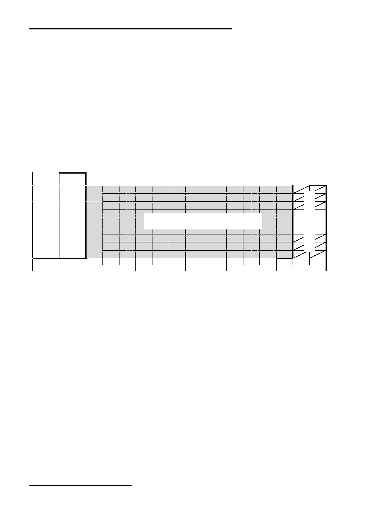
4.2.1 Display Memory Map
ROW
ROW
add.
no.
LCD Display (front view)
00h
1 st
01h
2 nd
02h
3 rd
:
:
160 x 160 pixels
9Dh
158 th
9Eh
159 th
9Fh
160 th
Column no.
1 st
2 nd
3 rd
4 th
5 th
6 th
157 th 158 th 159 th 160 th 161 st 162 nd
Column Address
25h
26h
59h
5Ah
Note:
*1. The above is based on:
- Mirror Y direction; LC[2]=1
- Normal X direction; LC[1]=0
*2. For details please refer to UC1698 datasheet
URL: www.topwaydisplay.com
Document Name: LM160160ACW-1-Manual-Rev0.2
Page: 7 of 12
TOPWAY
LCD Module User Manual
LM160160ACW-1
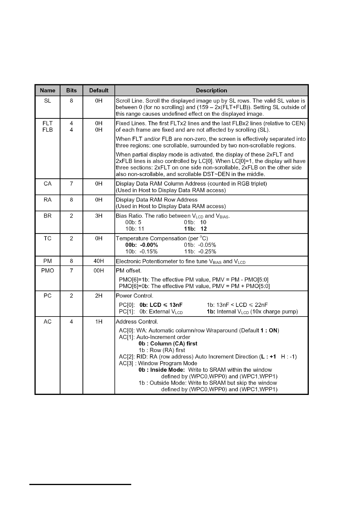
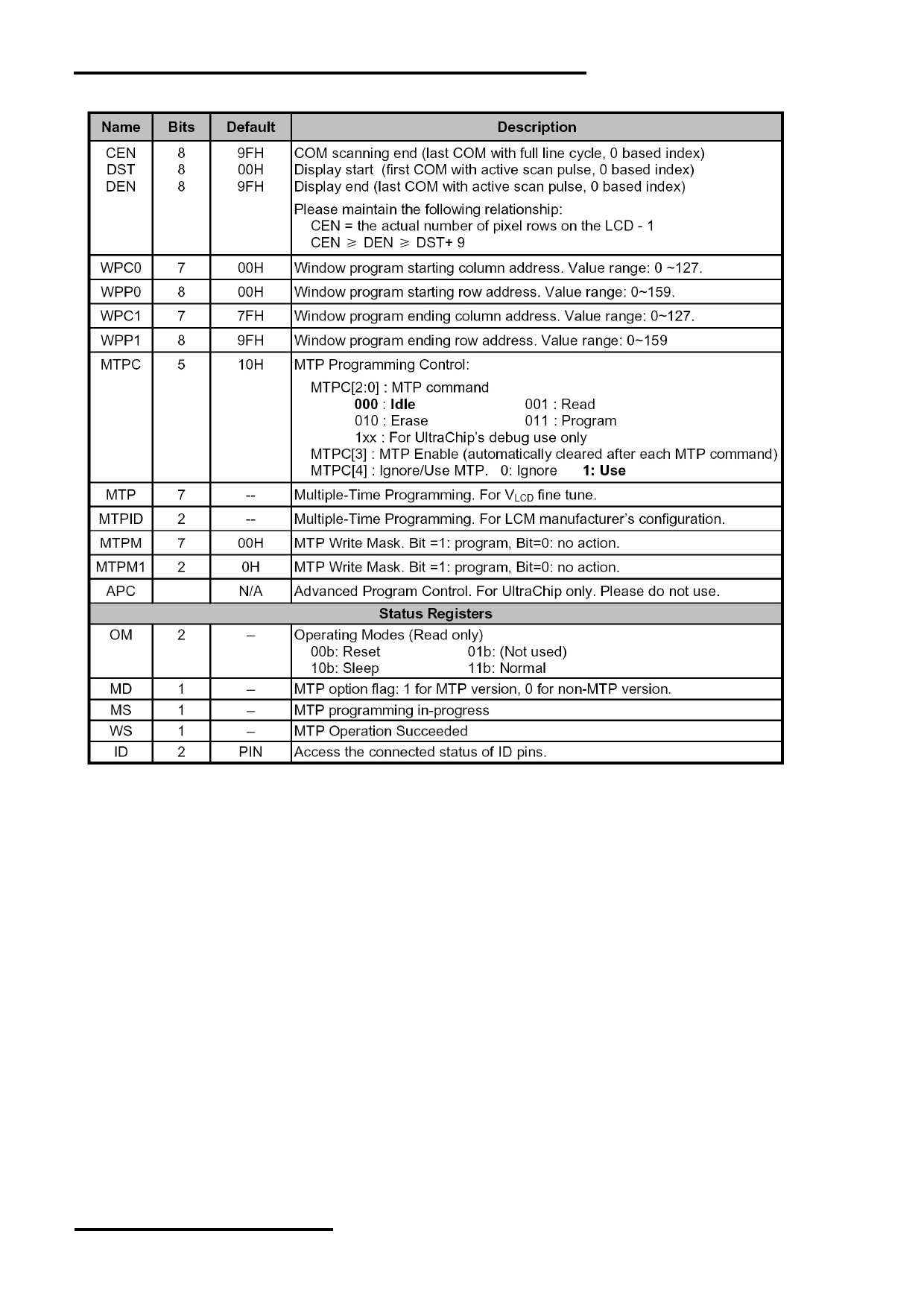
4.3 Display Commands
The LCD module contains register, which control the operation. These register can be modified by commands.
The following table is a summary of the control registers, their meaning and their default value.
4.3.1 Register Table
URL: www.topwaydisplay.com
Document Name: LM160160ACW-1-Manual-Rev0.2
Page: 8 of 12
TOPWAY
LCD Module User Manual
LM160160ACW-1
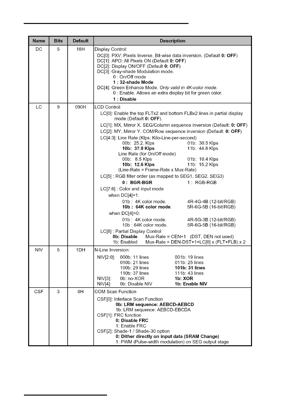
Register Table (continue)
URL: www.topwaydisplay.com
Document Name: LM160160ACW-1-Manual-Rev0.2
Page: 9 of 12
TOPWAY
LCD Module User Manual
LM160160ACW-1
Register Table (continue)
Note: Please refer to UC1698 data sheet for details
URL: www.topwaydisplay.com
Document Name: LM160160ACW-1-Manual-Rev0.2
Page: 10 of 12
TOPWAY
LCD Module User Manual
LM160160ACW-1
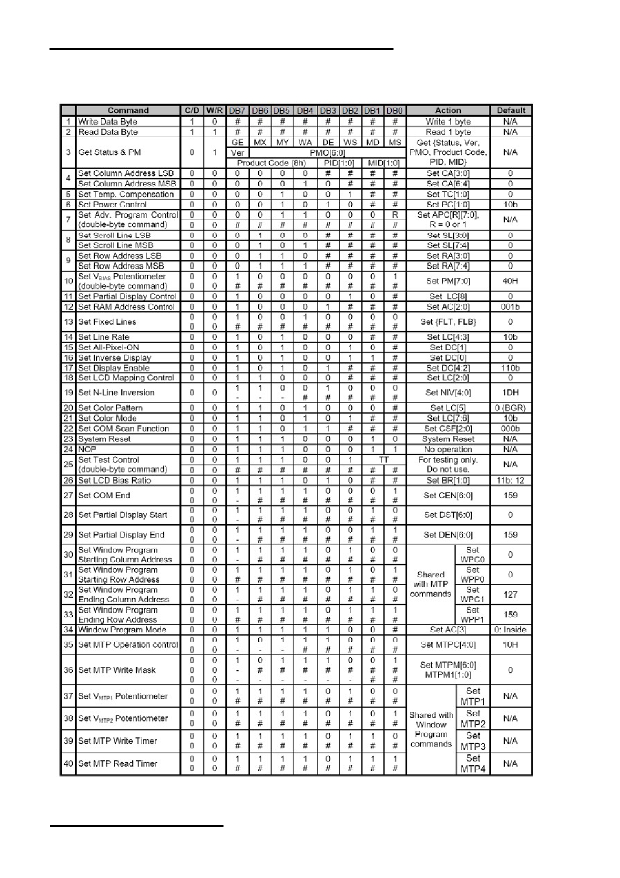
4.3.2 Command Table
The following is the list of host command supported.
Note:
Please refer to UC1698 data sheet for details
R/W=0 means it is a write function, R/W=1 means it is a read function
D/C=0 means it is a control data, D/C=1 means it is a display data
URL: www.topwaydisplay.com
Document Name: LM160160ACW-1-Manual-Rev0.2
Page: 11 of 12

TOPWAY
LCD Module User Manual
LM160160ACW-1
5. Design and Handling Precaution
Please refer to "LCD-Module-Design-Handling-Precaution.pdf".
URL: www.topwaydisplay.com
Document Name: LM160160ACW-1-Manual-Rev0.2
Page: 12 of 12