LM160160RCW
LCD Module User Manual
Prepared by:
Checked by:
Approved by:
Yaogang
Date: 2019-10-14
Date:
Date:
Rev. Descriptions
Release Date
0.1
Preliminary release
2018-03-23
0.2
Update Terminal Functions
2019-05-28
0.3
Adding Capacitance Withstand Voltage Value
2019-10-14
URL: www.topwaydisplay.com
Document Name: LM160160RCW-Manual-Rev0.3
Page: 1 of 13

TOPWAY
LCD Module User Manual
LM160160RCW
Table of Content
1. Basic Specifications ............................................................................................................... 3
1.1
Display Specifications ........................................................................................................ 3
1.2
Mechanical Specifications .................................................................................................. 3
1.3
Block Diagram ..................................................................................................................... 3
1.4
Terminal Functions ............................................................................................................. 4
2. Absolute Maximum Ratings ................................................................................................... 5
3. Electrical Characteristics ....................................................................................................... 5
3.1
DC Characteristics .............................................................................................................. 5
3.2
LED Backlight Circuit Characteristics ............................................................................... 5
3.3
AC Characteristics .............................................................................................................. 6
4. Function specifications ........................................................................................................ 10
4.1
Application circuit(Example) ............................................................................................ 10
4.2
Adjusting the Display Contrast ........................................................................................ 10
4.3
Resetting the LCD module ................................................................................................ 10
4.4
Display Commands ........................................................................................................... 11
5. Design and Handling Precaution ......................................................................................... 13
URL: www.topwaydisplay.com
Document Name: LM160160RCW-Manual-Rev0.3
Page: 2 of 13
TOPWAY
LCD Module User Manual
LM160160RCW
1. Basic Specifications
1.1 Display Specifications
1) LCD Display Mode
: FSTN, Positive, Transflective
2) Display Color
: Display Data = “1” : Dark Gray(*1)
: Display Data = “0” : Light Gray (*2)
3) Viewing Angle
: 6H
4) Driving Method
: 1/160 duty, 1/12 bias
5) Backlight
: White LED backlight
Note:
*1. Color tone may slightly change by Temperature and Driving Condition.
*2. The Color is defined as the inactive / background color
*3. Fine Contrast adjustment function is necessary in the application design for optimal display result
1.2 Mechanical Specifications
1) Outline Dimension
: 65.4 x 71.3 x 4.1mm (exclude FPC terminal)
(See attached Outline Drawing for details)
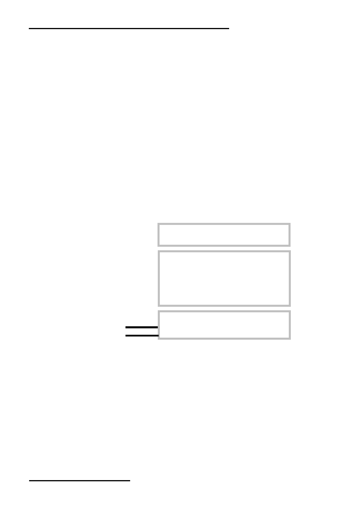
1.3 Block Diagram
BLA
BLK
Backlight Circuit
LCD Panel
160 × 160Pixels
VB0+,VB1+,VB1-,VB0-,VDD,VLCD
VSS
DB0~DB7
UC1628 or equivalent
/CS, /RST, D/C, /WR, /RD,BM1,BM0
URL: www.topwaydisplay.com
Document Name: LM160160RCW-Manual-Rev0.3
Page: 3 of 13
TOPWAY
LCD Module User Manual
LM160160RCW
1.4 Terminal Functions
Pin
Descriptions
No.
PIN Name
I/O
8080 mode
6800 mode
4-SPI mode
I2C mode
1
VSS
P
power supply,0V
2
VB0+
3
VB1+
LCD Bias Voltages. These are the voltage sources to provide SEG driving
P
4
VB1-
currents.
5
VB0-
6
VLCD
P
High voltage LCD Power Supply
7
VDD
P
power supply
8
VSS
P
power supply,0V
Bus mode: The interface bus mode is determined by BM[1:0]:
9
BM1
I
Mode
BM[1:0]
8080 (8-bit)
10
6800 (8-bit)
11
10
BM0
I
4-wire SPI w/ 8-bit token (S8)
01
2-wire SPI (I2C)
00
/WR=H,
R/W=H,E=H;
Not used,
Not used,
/RD=L;
Data or Status connect to VSS connect to
11
/RD ( E )
I
Data or Status read from the
VSS
read form the
LCD module
LCD module
R/W=L,E=H L;
/WR=L H,
Data or Status
/RD=H;
latch into the
LCD module
12
Data or
/WR ( R /W)
I
Instruction
latch into the
LCD module
Register Select
13
D/C
I
D/C = H, Transferring the Display Data
D/C = L, Transferring the Control Data
Chip Select
14
/CS
I
/CS=L, enable access to the LCD module
/CS=H, disable access to the LCD module
Reset signal
15
/RST
I
/RST = L, Initialization is executed
/RST = H, Normal running.
16
DB0( SCK )
8-bit Data bus;
In serial modes, connect DB[0]
17
DB1
Three state I/O terminal for
to SCK, DB[3] to SDAI for write
18
DB2
display data or instruction data
and DB[5:4] to SDAO for read.
19
DB3( SDAI )
when /CS=H, DB0~DB7=High
SDAI and SDAO may be
I/O
20
DB4( SDAO )
Impedance.
connected together if
21
DB5( SDAO )
necessary.
22
DB6
23
DB7
Connect unused pins to VSS.
24
VSS
P
power supply,0V
Note:
Please refer to the UC1628 data sheet for details
URL: www.topwaydisplay.com
Document Name: LM160160RCW-Manual-Rev0.3
Page: 4 of 13
TOPWAY
LCD Module User Manual
LM160160RCW
2. Absolute Maximum Ratings
Items
Symbol
Min.
Max.
Unit Condition
Supply Voltage
V DD
-0.3
+4.0
V
V SS = 0V
Input Voltage
V IN
-0.3
+4.0
V
V SS = 0V
Operating Temperature
T OP
-40
+70
C
No Condensation
Storage Temperature
T ST
-40
+80
C
No Condensation
Cautions:
Any Stresses exceeding the Absolute Maximum Ratings may cause substantial damage to the device. Functional
operation of this device at other conditions beyond those listed in the specification is not implied and prolonged exposure
to extreme conditions may affect device reliability.
3. Electrical Characteristics
3.1 DC Characteristics
V DD =3.3V ,V SS =0V, T OP =25 C
Items
Symbol
MIN.
TYP.
MAX.
Unit
Condition /
Application Pin
Operating Voltage
V DD
2.7
3.3
3.6
V
VDD
Input High Voltage
V IH
0.8xV DD
-
V DD
V
/RST, /CS, D/C,
Input Low Voltage
V IL
V SS
-
0.2xV DD
V
DB0~DB7, /RD, /WR
Operating Current
I DD
-
1.06
5.6
mA
VDD
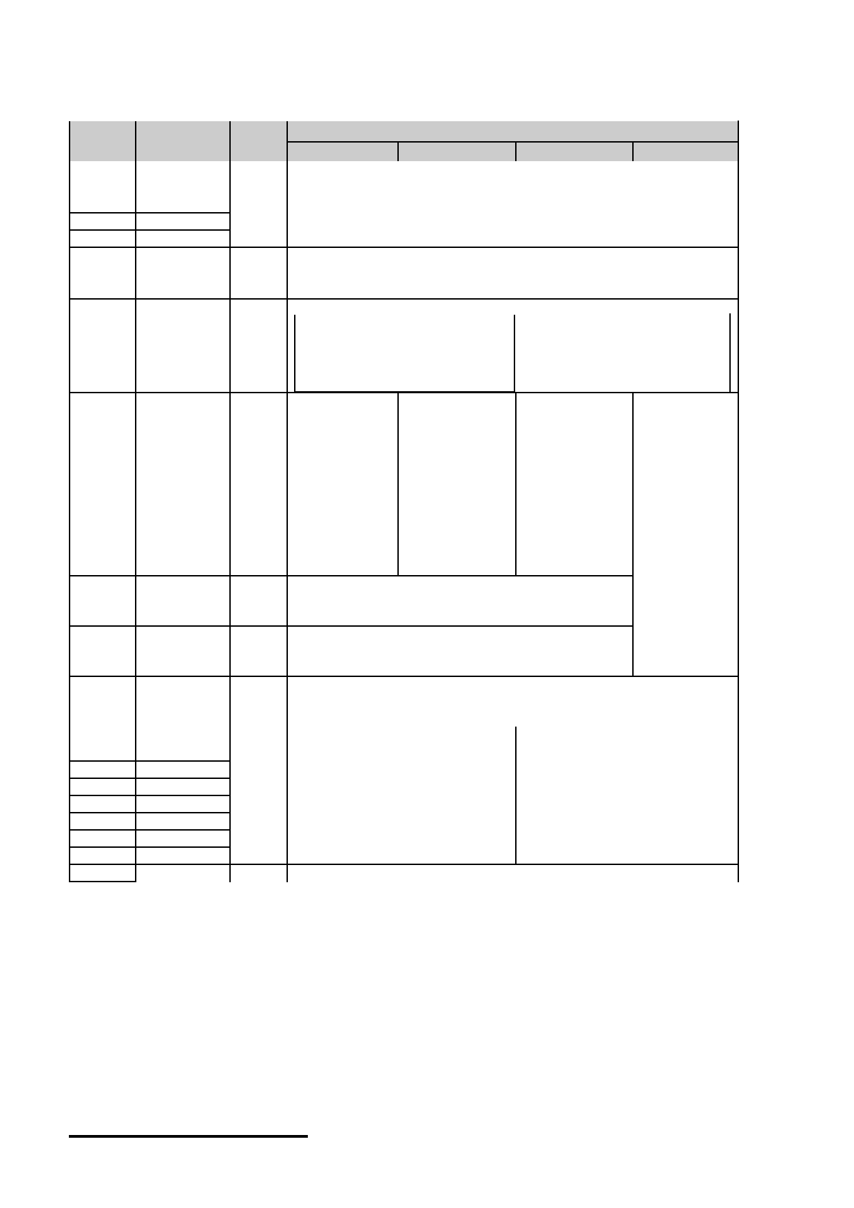
3.2 LED Backlight Circuit Characteristics
BLA=3.3V ,BLK=0V, T OP =25 C
Items
Symbol
MIN.
TYP.
MAX.
Unit
Applicable Pin
Forward Voltage
BLA
-
3.3
-
V
BLA
Forward Current
I BLA
-
68
80
mA
BLA
Cautions:
Exceeding the recommended driving current could cause substantial damage to the backlight and shorten its lifetime.
BLA
BLK
No. of LED = 4pcs
URL: www.topwaydisplay.com
Document Name: LM160160RCW-Manual-Rev0.3
Page: 5 of 13
TOPWAY
LCD Module User Manual
LM160160RCW
3.3 AC Characteristics
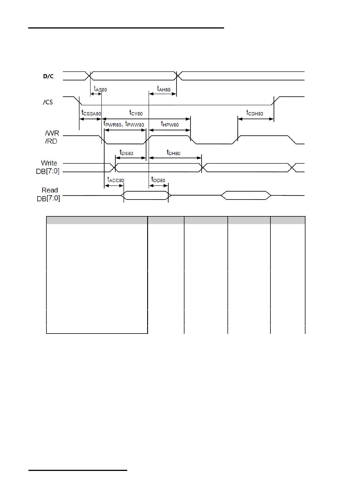
3.3.1 8080 Mode System Bus Timing
V DD =3.3V V SS =0V, T OP =25 C
Item
Symbol
MIN.
MAX.
Unit
Address setup time (D/C)
tas80
20
-
ns
Address hold time (D/C)
tah80
26
-
ns
System cycle time (read)
tcy80
560
-
ns
System cycle time(write)
tcy80
364
-
ns
Read pulse width
tpwr80
260
-
ns
Write pulse width
tpww80
163
-
ns
High pulse width (read)
thpw80
260
-
ns
High pulse width (write)
thpw80
163
-
ns
Data setup time
tds80
59
-
ns
Data hold time
tdh80
13
-
ns
Data access time
tacc80
-
260
ns
Data output disable time
tod80
70
ns
Chip select setup time
tcssa80
7
-
ns
Chip select hold time
tcsh80
7
-
ns
Note:
*1. Input signal rise/fall time should be less than 15ns .
*2. CL=100pF
*3.All timing is using 20% and 80% of VDD as the reference.
URL: www.topwaydisplay.com
Document Name: LM160160RCW-Manual-Rev0.3
Page: 6 of 13
TOPWAY
LCD Module User Manual
LM160160RCW
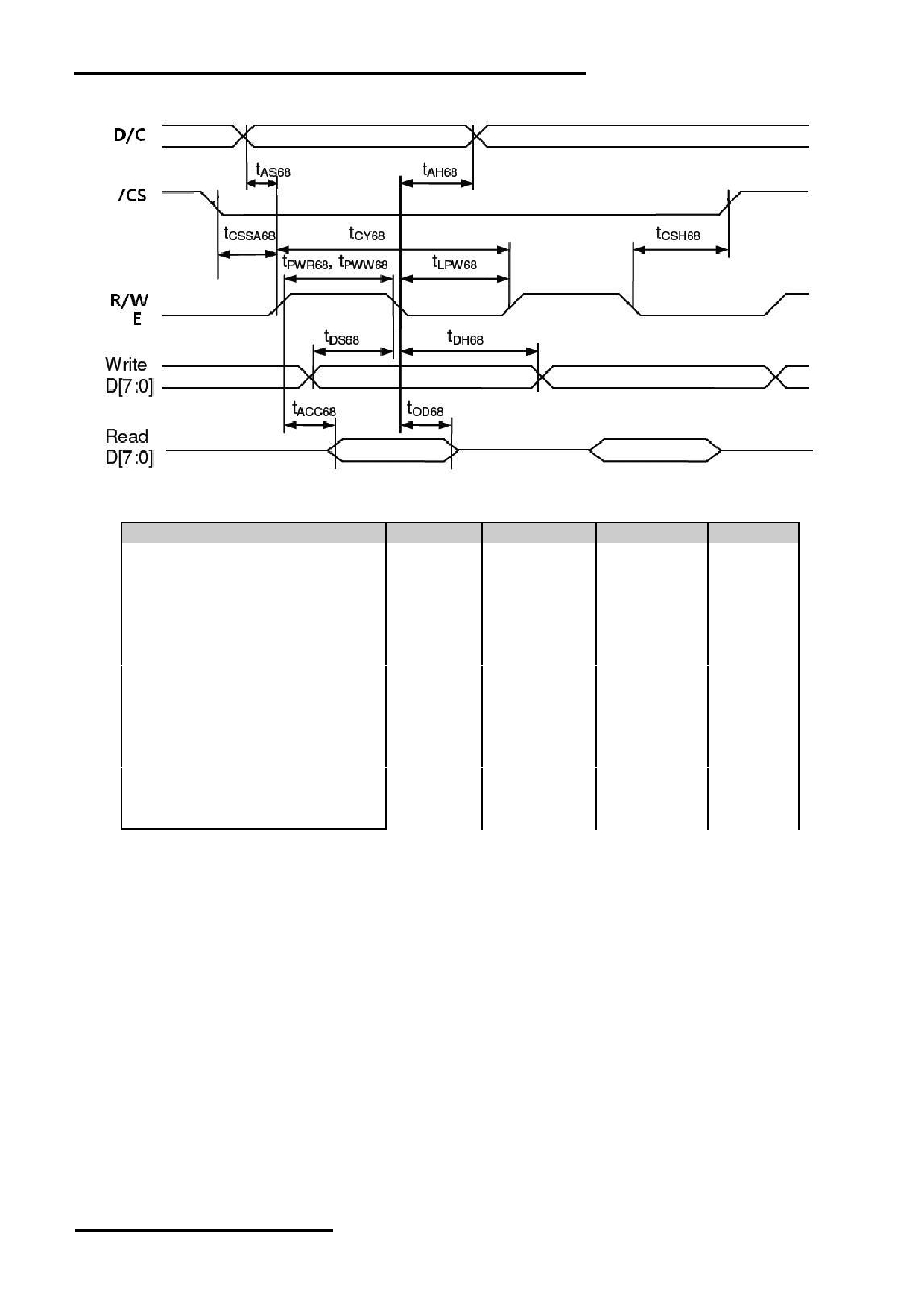
3.3.2 6800 Mode System Bus Timing
V DD =3.3V V SS =0V, T OP =25 C
Item
Symbol
MIN.
MAX.
Unit
Address setup time (D/C)
tAS68
20
-
ns
Address hold time (D/C)
tAH68
26
-
ns
System cycle time (read)
Tcy68
560
-
ns
System cycle time (write)
Tcy68
364
-
ns
Read pulse width
Tpwr68
260
-
ns
Write pulse width
Tpww68
163
-
ns
High pulse width (read)
Thpw68
260
-
ns
High pulse width (write)
Thpw68
163
-
ns
Data setup time
Tds68
59
-
ns
Data hold time
Tdh68
13
-
ns
Data access time
Tacc68
-
260
ns
Data output disable time
Tod68
70
ns
Chip select setup time
tCSSA68
7
-
ns
Chip select hold time
tCSH68
7
-
ns
Note:
*1. Input signal rise/fall time should be less than 15ns .
*2. CL=100pF
*3.All timing is using 20% and 80% of VDD as the reference.
URL: www.topwaydisplay.com
Document Name: LM160160RCW-Manual-Rev0.3
Page: 7 of 13
TOPWAY
LCD Module User Manual
LM160160RCW
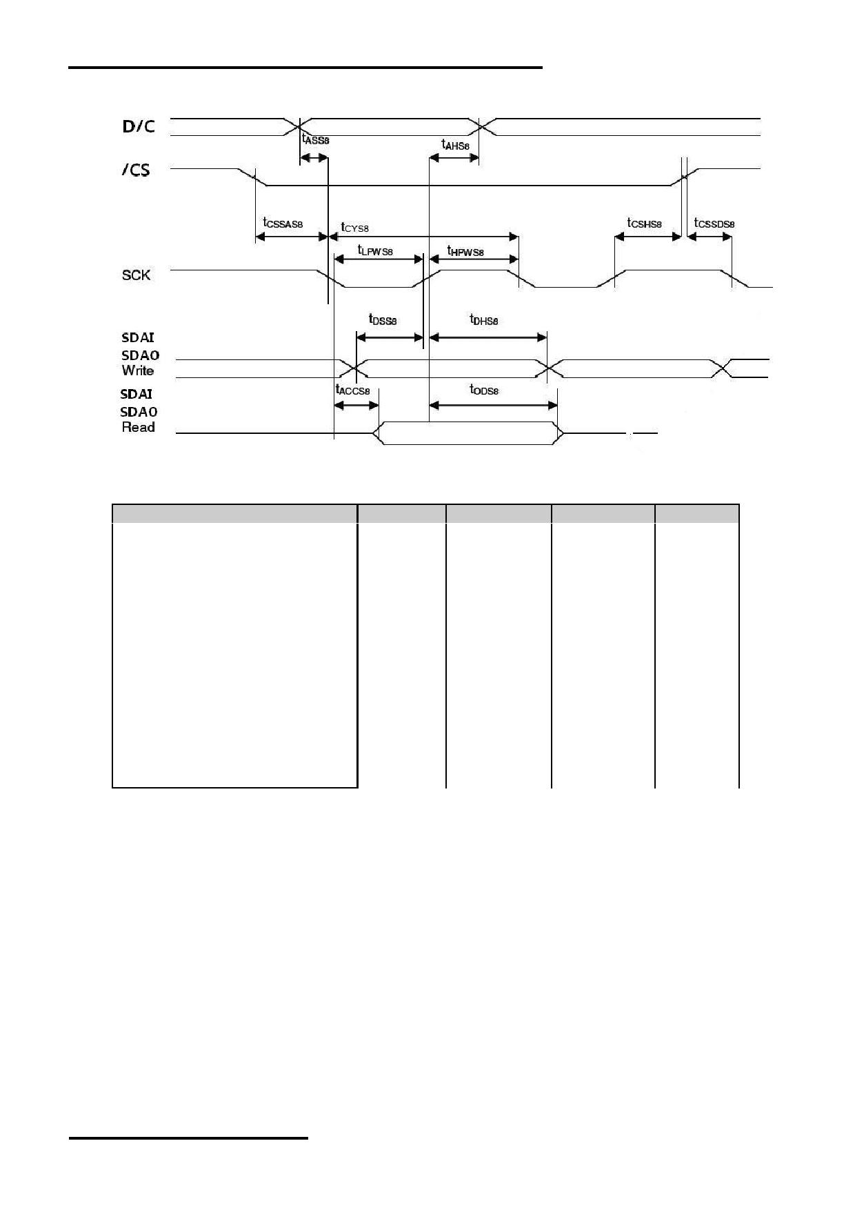
3.3.3 4-wire SPI w/ 8-bit token (S8)
V DD =3.3V V SS =0V, T OP =25 C
Item
Symbol
MIN.
MAX.
Unit
Address setup time (D/C)
Tass8
0
-
ns
Address hold time (D/C)
TAHs8
20
-
ns
System cycle time (read)
Tcys8
559
-
ns
System cycle time (write)
Tcys8
286
-
ns
Low pulse width(read)
tLPWS8
260
-
ns
Low pulse width(write)
tLPWS8
124
-
ns
High pulse width (read)
Thpws8
260
-
ns
High pulse width (write)
Thpws8
124
-
ns
Data setup time
Tdss8
33
-
ns
Data hold time
Tdhs8
20
-
ns
Data access time
Taccs8
-
260
ns
Data output disable time
Tods8
21
ns
Chip select setup time
tCSSAs8
7
-
ns
Chip select hold time
tCSHs8
20
-
ns
Note:
*1. Input signal rise/fall time should be less than 15ns .
*2. CL=100pF
*3.All timing is using 20% and 80% of VDD as the reference.
URL: www.topwaydisplay.com
Document Name: LM160160RCW-Manual-Rev0.3
Page: 8 of 13
TOPWAY
LCD Module User Manual
LM160160RCW
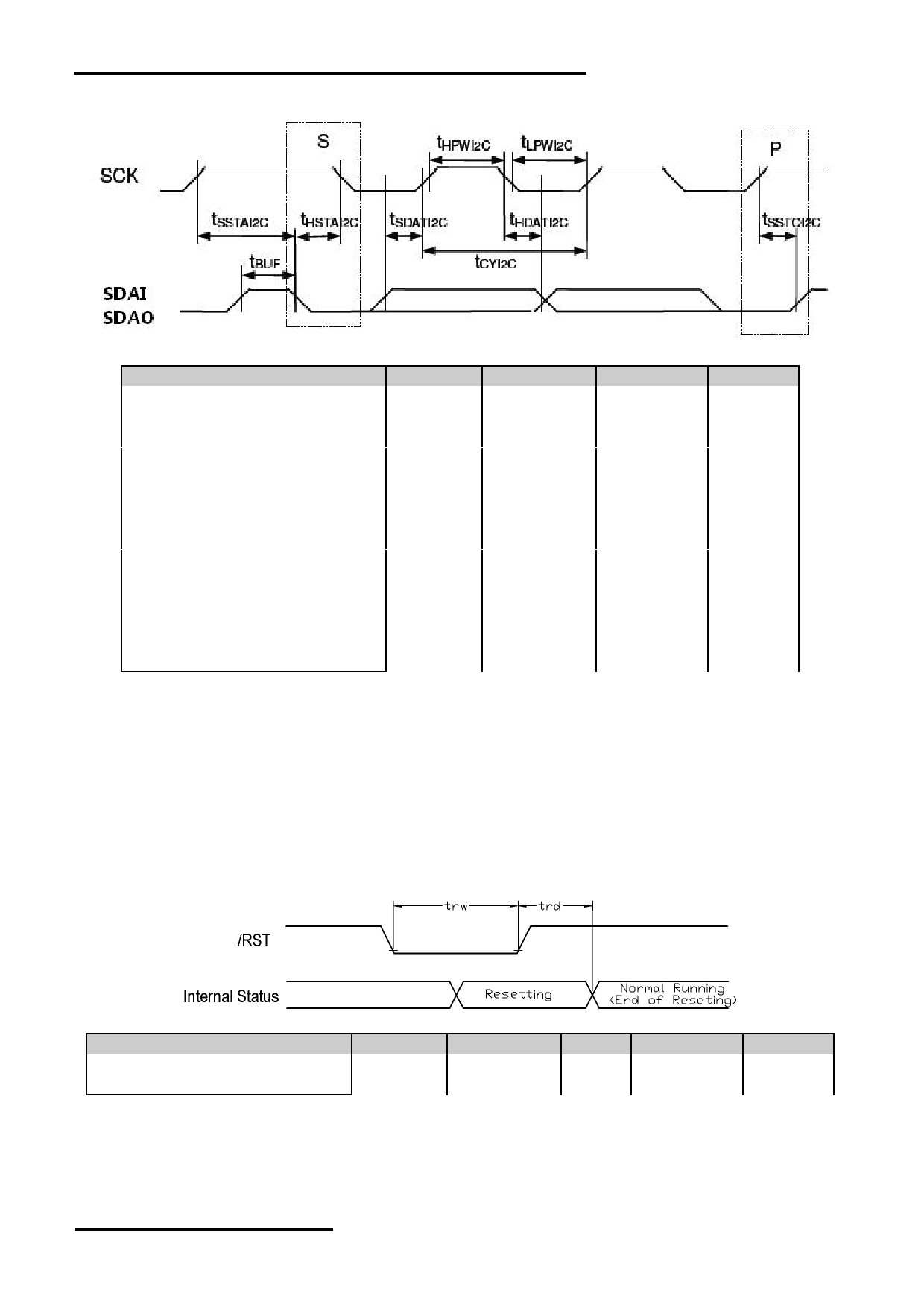
3.3.4 I2C
V DD =3.3V V SS =0V, T OP =25 C
Item
Symbol
MIN.
MAX.
Unit
SCK cycle time(read)
tCYI2C
689
-
ns
SCK cycle time(write)
tCYI2C
299
-
ns
Low pulse width(read)
tLPWI2C
325
-
ns
Low pulse width(write)
tLPWI2C
130
-
ns
High pulse width(read)
tHPWI2C
325
-
ns
High pulse width(write)
tHPWI2C
130
-
ns
Rise time and fall time
tr, tf
-
-
ns
Data setup time
tSSDAI2C
72
-
ns
Data hold time
tHDAI2C
13
-
ns
START Setup time
tSSTAI2C
13
-
ns
START Hold time
tHSTAI2C
72
-
ns
STOP setup time
tSSTOI2C
13
-
ns
Bus Free time between
STOP and START condition
tBUF
98
-
ns
Note:
*1. Input signal rise/fall time should be less than 15ns .
*2. CL=100pF
*3.All timing is using 20% and 80% of VDD as the reference.
3.3.5 Reset Timing
V DD =3.3V,V SS =0V, T OP =25 C
Item
Symbol
MIN.
TYP.
MAX.
Unit
Reset LOW pulse width
trw
4
-
-
us
Internal Resetting time
trd
150
-
-
ms
Note:
*1.All timing is using 20% and 80% of VDD as the reference.
URL: www.topwaydisplay.com
Document Name: LM160160RCW-Manual-Rev0.3
Page: 9 of 13
TOPWAY
LCD Module User Manual
LM160160RCW
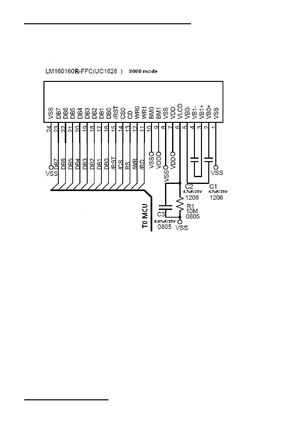
4. Function specifications
4.1 Application circuit(Example)
Note:
Please refer to the UC1628 data sheet for details
4.2 Adjusting the Display Contrast
This LCD module equipped with latest digital contrast adjustment function.
Its display contrast could be adjusted by MCU command.
(Please see the command tables for details)
It is recommended to provide a contrast adjustment interface for end-user,
where the best display result could meet the individual preference in mass production.
4.3 Resetting the LCD module
The LCD module should be initialized by using /RST terminal.
While turning on the VDD and VSS power supply, maintain /RST terminal at LOW level. After the
power supply stabilized, release the reset terminal (/RST=HIGH)
URL: www.topwaydisplay.com
Document Name: LM160160RCW-Manual-Rev0.3
Page: 10 of 13

TOPWAY
LCD Module User Manual
LM160160RCW
4.4 Display Commands
The LCD module contains register, which control the operation. These register can be modified by commands.
The following table is a summary of the control registers, their meaning and their default value.
4.4.1 Command Table
The following is the list of host command supported.
URL: www.topwaydisplay.com
Document Name: LM160160RCW-Manual-Rev0.3
Page: 11 of 13

TOPWAY
LCD Module User Manual
LM160160RCW
Note:
Please refer to UC1628 data sheet for details
R/W=0 means it is a write function, R/W=1 means it is a read function
D/C=0 means it is a control data, D/C =1 means it is a display data
URL: www.topwaydisplay.com
Document Name: LM160160RCW-Manual-Rev0.3
Page: 12 of 13

TOPWAY
LCD Module User Manual
LM160160RCW
5. Design and Handling Precaution
Please refer to "LCD-Module-Design-Handling-Precaution.pdf".
URL: www.topwaydisplay.com
Document Name: LM160160RCW-Manual-Rev0.3
Page: 13 of 13