LM2088ECW-9
LCD Module User Manual
Prepared by:
Checked by:
Approved by:
Chen Rili
Date: 2017-08-31
Date:
Date:
Rev. Descriptions
Release Date
0.1
New release
2017-08-31
URL: www.topwaydisplay.com
Document Name: LM2088ECW-9-Manual-Rev0.1
Page: 1 of 11

TOPWAY
LCD Module User Manual
LM2088ECW-9
Table of Content
1. Basic Specifications .............................................................................................................. 3
1.1
Display Specifications ............................................................................................................................ 3
1.2
Mechanical Specifications ..................................................................................................................... 3
1.3
Block Diagram ....................................................................................................................................... 3
1.4
Terminal Functions ................................................................................................................................ 4
2. Absolute Maximum Ratings .................................................................................................. 5
3. Electrical Characteristics ...................................................................................................... 5
3.1
DC Characteristics ................................................................................................................................. 5
3.2
LED Backlight Circuit Characteristics .................................................................................................... 5
3.3
AC Characteristics ................................................................................................................................. 6
3.4
Reset Timing .......................................................................................................................................... 7
4. Function Specifications ......................................................................................................... 8
4.1
Adjusting the Display Contrast............................................................................................................... 8
4.2
Resetting the LCD module ..................................................................................................................... 8
4.3
Jumper Functions .................................................................................................................................. 8
4.4
Display Pixel Map .................................................................................................................................. 8
4.5
Command Summary .............................................................................................................................. 9
4.6
Initialization Setting Example ............................................................................................................... 10
5. Design and Handling Precaution ........................................................................................ 11
URL: www.topwaydisplay.com
Document Name: LM2088ECW-9-Manual-Rev0.1
Page: 2 of 11
TOPWAY
LCD Module User Manual
LM2088ECW-9
1. Basic Specifications
1.1 Display Specifications
1) LCD Display Mode
: FSTN, Positive, Transmissive
2) Display Color
: Display Data = “1” : Dark Gray (*1)
: Display Data = “0” : Light Gray (*2)
3) Viewing Angle
: 6 H
4) Driving Method
: 1/240 duty, 1/14 bias
5) Backlight
: White LED backlight
Note:
*1. Color tone may slightly change by Temperature and Driving Condition.
*2. The Color is defined as the inactive / background color
*3. Fine Contrast adjustment function is necessary in application design for optimal display result
1.2 Mechanical Specifications
1) Outline Dimension
: 160.0 x 109.0 x 11.2 MAX.
see attached Outline Drawing for details
1.3 Block Diagram
BLA
BLK
Backlight Circuit
320 x 240 pixels
LCD Panel
VDD
VOUT
Booster &
V0
SEGMENT
SEGMENT
Power Circuit
VSS
Driver
Driver
/WR,/RD,A0, /CS,/RST
DB0~DB7
S1D13700
/WAIT
or equivalent
URL: www.topwaydisplay.com
Document Name: LM2088ECW-9-Manual-Rev0.1
Page: 3 of 11
TOPWAY
LCD Module User Manual
LM2088ECW-9
1.4 Terminal Functions
Pin No.
Pin
K1&K4
K5
K3
Name
I/O
Descriptions
1
1
15
VSS
Power 0V Power Supply, GND
2
2
14
VDD
Power Positive Power Supply
3
3
17
V0
Input
LCD Contrast Reference Input
4
5
3
/WR
Input
Write enable input, active LOW
5
6
2
/RD
Input
Read enable input, active LOW
6
15
4
/CS
Input
Chip Select Signal
/CS=LOW: Data IO is enabled
7
4
5
A0
Input
Data Type Select
A0=H: command write, display data or cursor add read
A0=L: status flag read, display data or parameter write
8
16
1
/RST
Input
Reset Signal:
/RES = L, Reset the LCD Module
/RES = H, Normal Running
9
7
6
DB0
I/O
8-bit bi-directional data bus
:
:
:
:
16
14
13
DB7
17
-
-
/WAIT
Output Wait signal (*1)
18
17
16
VOUT
Power Power Booster Output for V0
19
19
23
BLA
Power Positive Power Supply for LED backlight
20
20
24
BLK
Power Negative Power Supply for LED backlight
-
18
-
SEL1
Input
80 mode or 68 mode selection(*2)
-
21
18
NC
-
NC
-
22
19
NC
-
NC
-
-
20
NC
-
NC
-
-
21
NC
-
NC
-
-
22
NC
-
NC
note:
*1.
If there is no read write activity, /WAIT will be in HZ state.
*2.
SEL1 fixed to low (80 mode) by internal Jumper JP8
URL: www.topwaydisplay.com
Document Name: LM2088ECW-9-Manual-Rev0.1
Page: 4 of 11
TOPWAY
LCD Module User Manual
LM2088ECW-9
2. Absolute Maximum Ratings
Items
Symbol
Min.
Max.
Unit
Condition
Supply Voltage
V DD
0
+7.0
V
V SS = 0V
Input Voltage
V IN
V SS -0.3
V DD +0.3
V
V SS = 0V
Operating Temperature
T OP
-20
+70
C
No Condensation
Storage Temperature
T ST
-30
+80
C
No Condensation
Cautions:
Any Stresses exceeding the Absolute Maximum Ratings may cause substantial damage to the device. Functional operation of this
device at other conditions beyond those listed in the specification is not implied and prolonged exposure to extreme conditions may
affect device reliability.
3. Electrical Characteristics
3.1 DC Characteristics
V SS =0V, V DD =5.0V, T OP =25 C
Items
Symbol
MIN.
TYP.
MAX.
Unit Applicable Pin
Operating Voltage
V DD
4.5
5.0
5.5
V
VDD
DB0~DB7, /WR,
Input High Voltage
V IN
0.8xVDD
-
VDD
V
/RD, /CS, A0, /RST
DB0~DB7, /WR,
Input Low Voltage
V IN
VSS
-
0.15xVDD
V
/RD, /CS, A0, /RST
Operating Current
I DD
-
24.4
62
mA VDD
Note:
*1. Frame freq. at 131Hz
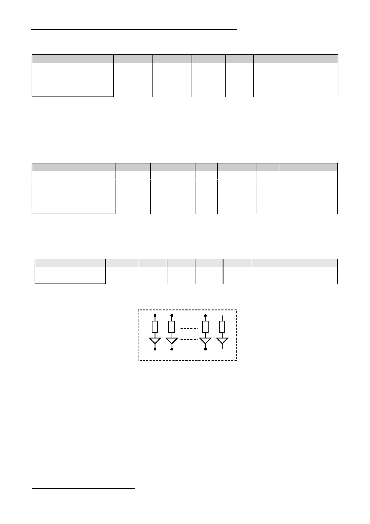
3.2 LED Backlight Circuit Characteristics
BLK=0V, BLA=5.0V, T OP =25 C
Items
Symbol
MIN.
TYP.
MAX.
Unit
Applicable Pin
Forward Voltage
BLA
-
5.0
-
V
BLA
Forward Current
I BLA
-
145
180
mA
BLA
Cautions:
Exceeding the recommended driving current could cause substantial damage to the backlight and shorten its lifetime.
BLA
BLK
No. of LED = 9pcs
URL: www.topwaydisplay.com
Document Name: LM2088ECW-9-Manual-Rev0.1
Page: 5 of 11
TOPWAY
LCD Module User Manual
LM2088ECW-9
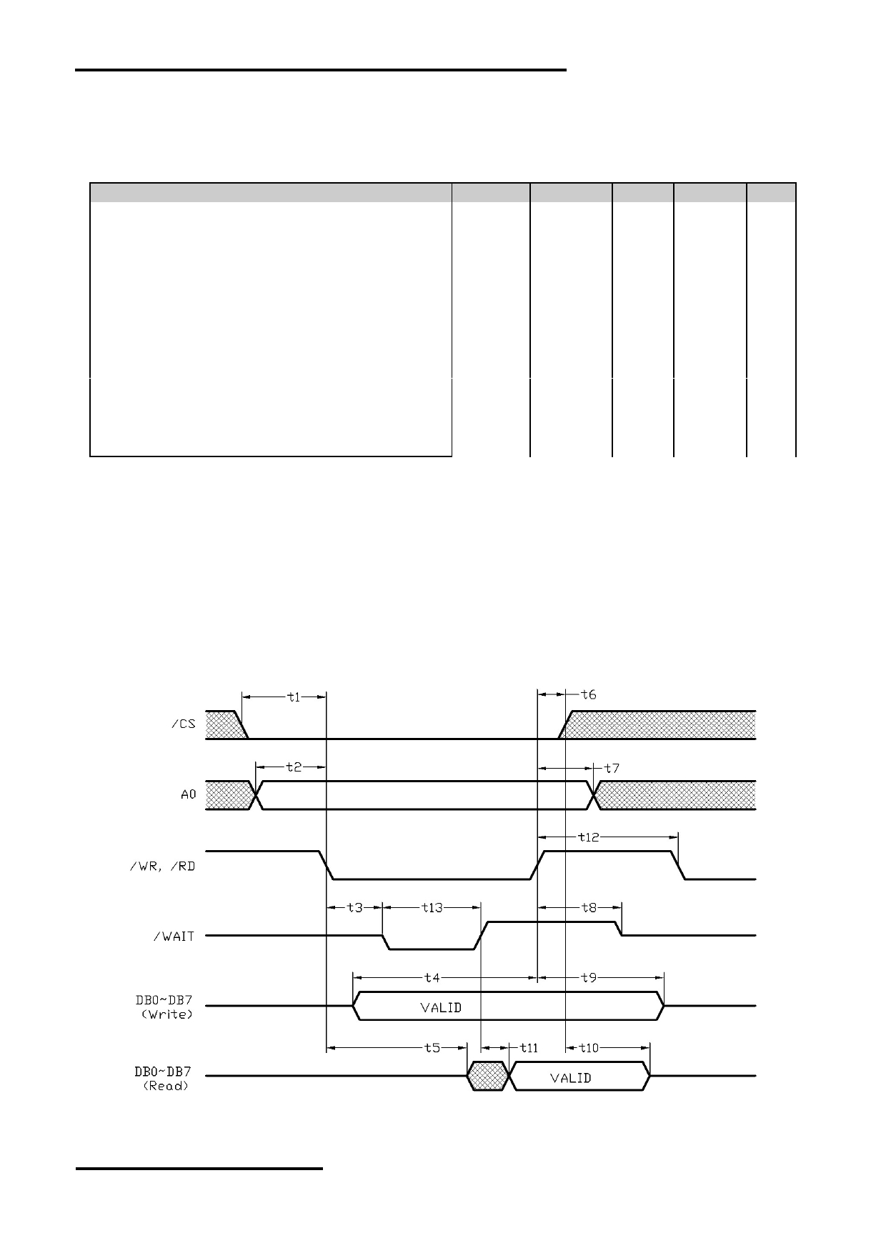
3.3 AC Characteristics
3.3.1 8080 Mode
V SS =0V, V DD =5.0V, T OP =25 C
Item
Symbol
MIN.
TYP.
MAX.
Unit
/CS setup time
t1
7
-
-
ns
A0 setup time
t2
7
-
-
ns
/WR, /RD falling edge to /WAIT driven low
t3
1.6
-
20
ns
D[7:0] setup time to /WR rising edge (write cycle)
t4
(*2)
-
-
ns
/RD falling edge to D[7:0] driven (read cycle)
t5
4
ns
/CS hold time
t6
9
-
-
ns
A0 hold time
t7
9
-
-
ns
/RD, /WR rising edge to WAIT# high impedance
t8
1.6
-
13
ns
D[7:0] hold time from /WR rising edge (write cycle)
t9
6.5
-
-
ns
D[7:0] hold time from /CS rising edge (read cycle)
t10
2.4
-
18
ns
/WAIT rising edge to valid Data
t11
-
-
(*3)
ns
/RD, /WR pulse inactive time
t12
(*4)
-
-
ns
/WAIT pulse active time
t13
-
-
(*5)
ns
Note:
*1. Ts
= System clock period
*2. t4min = 2Ts + 5
*3. t11max = 1Ts + 7 (for 5.0V)
*4. t12min = 1Ts (for a read cycle followed by a read or write cycle)
= 2Ts + 2 (for a write cycle followed by a write cycle)
= 5Ts + 2 (for a write cycle followed by a read cycle)
*5. t13max = 4Ts + 2
*6. Input signal rise/fall time should be less than 4.5ns
*7. for details, please see the S1D13700 data sheet
Bus Timing Diagram
URL: www.topwaydisplay.com
Document Name: LM2088ECW-9-Manual-Rev0.1
Page: 6 of 11
TOPWAY
LCD Module User Manual
LM2088ECW-9
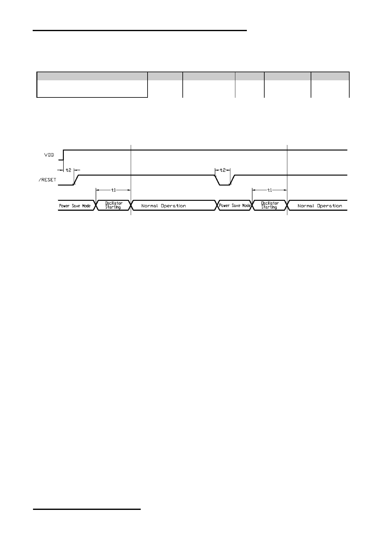
3.4 Reset Timing
V SS =0V, V DD =5.0V, T OP =25 C
Item
Symbol
MIN.
TYP.
MAX.
Unit
Oscillator Stable Delay (*1)
t1
4.0
-
-
ms
Reset Pulse Duration (*2)
t2
1.3
-
-
ms
note:
*1. A delay is required after exiting power save mode. Writing the SYSTEM SET command will exit power
save mode and start the internal oscillator.
*2. It requires a reset pulse after power-on in order to re-initialize its internal state.
Reset Timing Diagram
URL: www.topwaydisplay.com
Document Name: LM2088ECW-9-Manual-Rev0.1
Page: 7 of 11
TOPWAY
LCD Module User Manual
LM2088ECW-9
4. Function Specifications
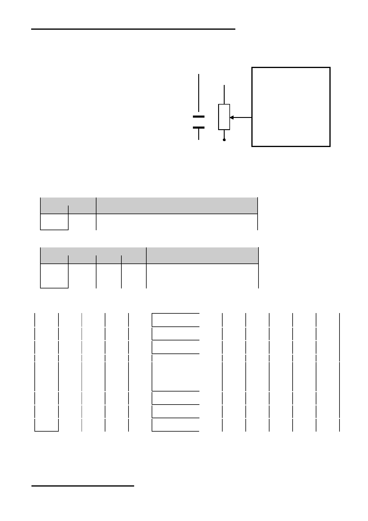
4.1 Adjusting the Display Contrast
A Variable-Resistor must be connected to the
VDD
LCD module for providing a reference to V0.
Adjusting the VR will result the change of
VOUT
LCD display contrast.
The recommended value of VR is 25k to 50k
VR
V0
VSS
4.2 Resetting the LCD module
The LCD module should be initialized by hardware reset, using /RST terminal.
4.3
Jumper Functions
4.3.1 Interfacing Setting
Jumper
JP9
JP8
Function Description
Open
Close 8080 mode selected <default>
Close
Open 6800 mode selected
4.3.2 Clock Divider Setting
Jumper
JP4
JP5
JP6
JP7 Function Description
Open
Close Open Close 1/4 clock divider <default>
Close
Open Open Close 1/8 clock divider
Open
Close Close Open 1/16 clock divider
4.4 Display Pixel Map
1,1
2,1
3,1
4,1
5,1
316,1
317,1
318,1
319,1
320,1
(D7)
(D6)
(D5)
(D4)
(D3)
- - -
- - -
(D4)
(D3)
(D2)
(D1)
(D0)
1,2
2,2
3,2
4,2
5,2
316,2
317,2
318,2
319,2
320,2
(D7)
(D6)
(D5)
(D4)
(D3)
- - -
- - -
(D4)
(D3)
(D2)
(D1)
(D0)
1,3
2,3
3,3
4,3
5,3
316,3
317,3
318,3
319,3
320,3
(D7)
(D6)
(D5)
(D4)
(D3)
- - -
- - -
(D4)
(D3)
(D2)
(D1)
(D0)
:
:
:
:
:
:
:
:
:
:
:
:
:
:
:
:
:
:
:
:
:
:
:
:
:
:
:
:
:
:
:
:
:
:
:
:
1,238
2,238
3,238
4,238
5,238
316,238 317,238 318,238 319,238 320,238
(D7)
(D6)
(D5)
(D4)
(D3)
- - -
- - -
(D4)
(D3)
(D2)
(D1)
(D0)
1,239
2,239
3,239
4,239
5,239
316,239 317,239 318,239 319,239 320,239
(D7)
(D6)
(D5)
(D4)
(D3)
- - -
- - -
(D4)
(D3)
(D2)
(D1)
(D0)
1,240
2,240
3,240
4,240
5,240
316,240 317,240 318,240 319,240 320,240
(D7)
(D6)
(D5)
(D4)
(D3)
- - -
- - -
(D4)
(D3)
(D2)
(D1)
(D0)
Pixel mapping (Top View)
Note:
*1.
Based on the top view of the LCD module,
the 1, 1 (x, y) pixel is the upper-left pixel;
the 320, 240 (x, y) pixel is the lower-right pixel.
*2.
For the details of memory mapping please refer to S1D13700 datasheet.
URL: www.topwaydisplay.com
Document Name: LM2088ECW-9-Manual-Rev0.1
Page: 8 of 11

TOPWAY
LCD Module User Manual
LM2088ECW-9
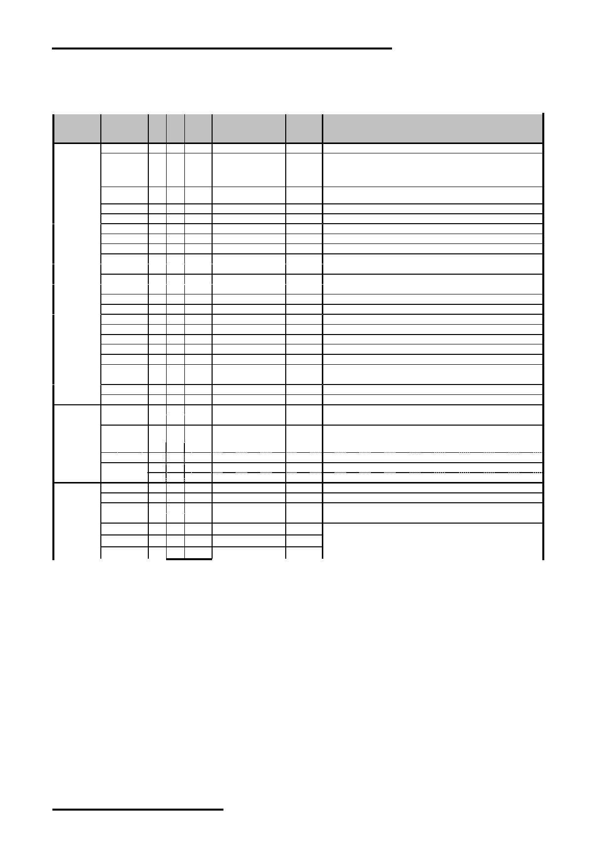
4.5 Command Summary
Para-
Command meter
HEX Descriptions
SYSTEM
-
1 1 0 0
1
0
0
0
0
0
0
40 Init device and display (with 8 parameters)
SET
P1
0 1 0 0
0
IV
1 W/S M2
0
M0
**
M0=0: internal CG ROM
M0=1: internal CG RAM
M2=0: 8-pixel char height
M2=1: 16-pixel char height
W/S=0: single panel drive
W/S=1: dual panel drive
IV=0: Screen top-line correction
IV=1: No screen top-line correction
P2
0 1 0 MOD 0
0
0
FX
**
FX=Horizontal Char Size in pixels – 1 (define the horizontal char size)
MOD=0: 16-line AC drive
MOD=1: two frame AC drive
P3
0 1 0 0
0
0
0
FY
**
FY=Vertical Char Size in pixels – 1 (define the vertical char size)
P4
0 1 0
C/R
**
C/R: Character Bytes per Row
P5
0 1 0
TC/R
**
TC/R: Total Char Bytes per Row (including horizontal blanking)
P6
0 1 0
L/F
**
L/F: Lines per Frame
P7
0 1 0
APL
**
APL: Horizontal address range of the virtual screen (low byte)
P8
0 1 0
APH
**
APH: Horizontal address range of the virtual screen (high byte)
POWER
-
1 1 0 0
1
0
1
0
0
1
1
53 Power Save Mode Enable
SAVE
DISP
-
1 1 0 0
1
0
1
1
0
0
D 58 / 59 Enable and disable display and display flashing (with 1 parameter)
ON/OFF
D=0: Display OFF
D=1: Display ON
P1
0 1 0 FP5 FP4 FP3 FP2 FP1 FP0 FC1 FC0
**
Each pair of bit in FP sets the attributes of one screen block
SCROLL
-
1 1 0 0
1
0
0
0
1
0
0
44 Set display start address and display regions (with 8 or 10 parameters)
P1
0 1 0 A7 A6 A5 A4 A3 A2 A1 A0
**
Screen Block 1 Start Address (SAD1) LSB
P2
0 1 0 A15 A14 A13 A12 A11 A10 A9 A8
**
Screen Block 1 Start Address (SAD1) MSB
P3
0 1 0 L7 L6 L5 L4 L3 L2 L1
L0
**
Screen Block 1 Size Register (SL1)
P4
0 1 0 A7 A6 A5 A4 A3 A2 A1 A0
**
Screen Block 2 Start Address (SAD2) LSB
P5
0 1 0 A15 A14 A13 A12 A11 A10 A9 A8
**
Screen Block 2 Start Address (SAD2) MSB
P6
0 1 0 L7 L6 L5 L4 L3 L2 L1
L0
**
Screen Block 2 Size Register (SL2)
P7
0 1 0 A7 A6 A5 A4 A3 A2 A1 A0
**
Screen Block 3 Start Address (SAD3) LSB
P8
0 1 0 A15 A14 A13 A12 A11 A10 A9 A8
**
Screen Block 3 Start Address (SAD3) MSB
P9
0 1 0 A7 A6 A5 A4 A3 A2 A1 A0
**
Screen Block 4 Start Address (SAD4) LSB
(for dual panel drive and two layer config are select)
P10 0 1 0 A15 A14 A13 A12 A11 A10 A9 A8
**
Screen Block 4 Start Address (SAD4) MSB
(for dual panel drive and two layer config are select)
CSRFORM
-
1 1 0 0
1
0
1
1
1
0
1
5D Set cursor type (with 2 parameters)
P1
0 1 0 0
0
0
0
X3
X2
X1
X0
**
CRX
P2
0 1 0 CM 0
0
0
Y3
Y2
Y1
Y0
**
CRY
CM=0: underscore cursor; CM=1: block cursor
CSRDIR
-
1 1 0 0
1
0
0
1
1 CD1 CD0 4C~4F Set Direction of Cursor movement
CD=00: Right; CD=01: Left,; CD=10: Up; CD=11: Down
OVLAY
-
1 1 0 0
1
0
1
1
0
1
1
5B Set display overlay format (with 1 parameters)
P1
0 1 0 0
0
0 OV DM2 DM1 MX1 MX0
**
CGRAM
-
1 1 0 0
1
0
1
1
1
0
0
5C Set Start address of char generator RAM (with 2 parameters)
ADR
P1
0 1 0 A7 A6 A5 A4 A3 A2 A1 A0
**
SAGL
P2
0 1 0 A15 A14 A13 A12 A11 A10 A9 A8
**
SAGH
HDOT SCR
-
1 1 0 0
1
0
1
1
0
1
0
5A Set horizontal scroll position (with 1 parameters)
P1
0 1 0 0
0
0
0
0 D2 D1 D0
**
CSRW
-
1 1 0 0
1
0
0
0
1
1
0
46 Set cursor address (with 2 parameters)
P1
0 1 0 A7 A6 A5 A4 A3 A2 A1 A0
**
CSRL
P2
0 1 0 A15 A14 A13 A12 A11 A10 A9 A8
**
CSRH
CSRR
-
1 1 0 0
1
0
0
0
1
1
1
47 Read Cursor Address (with 2 parameters)
P1
1 0 1 A7 A6 A5 A4 A3 A2 A1 A0
**
CSRL
P2
1 0 1 A15 A14 A13 A12 A11 A10 A9 A8
**
CSRH
GRAY
-
1 1 0 0
1
1
0
0
0
0
0
60 select the gray scale depth (in bits-per-pixel)
SCALE
P1
0 1 0 0
0
0
0
0
0 BPP1 BPP2
**
BPP=00: 1 bits-per-pixel; BPP=01: 2 bits-per-pixel;
BPP=10: 4 bits-per-pixel; BPP=01: reserved
MWRITE
-
1 1 0 0
1
0
0
0
0
1
0
42 Write to display memory (with n parameters)
P1
0 1 0
Memory Data
**
Display memory data
:
: : :
:
**
Pn
0 1 0
Memory Data
**
MREAD
-
1 1 0 0
1
0
0
0
0
1
1
43 Read from display memory (with n parameters)
P1
1 0 1
Memory Data
**
Display memory data
:
: : :
:
**
Pn
1 0 1
Memory Data
**
Note:
For details please refer to S1D13700 datasheet.
URL: www.topwaydisplay.com
Document Name: LM2088ECW-9-Manual-Rev0.1
Page: 9 of 11
TOPWAY
LCD Module User Manual
LM2088ECW-9
4.6 Initialization Setting Example
The following setting should be issue to LCD module after hardware reset.
(example could be adjusted if necessary.)
Value
Command Parameter
(binary)
HEX Descriptions
SYSTEM
-
1
1
0
0100 0000
40
Init device and display (with 8 parameters)
SET
P1
0
1
0
0011 0000
30
M0=0: internal CG ROM
M2=0: 8-pixel char height
W/S=0: single panel drive
IV=1: No screen top-line correction
P2
0
1
0
1000 0111
87
FX=7: the horizontal char size=7+1=8
WF=1: two frame AC drive
P3
0
1
0
0000 0111
07
FY=7: the vertical char size=7+1=8
P4
0
1
0
0010 1000
28
C/R: Character Bytes per Row
P5
0
1
0
0100 1001
47
TC/R: Total Char Bytes per Row (including horizontal blanking)
P6
0
1
0
1110 1111
EF
L/F: Lines per Frame
P7
0
1
0
0010 1000
28
APL: Horizontal address range of the virtual screen (low byte)
P8
0
1
0
0000 0000
00
APH: Horizontal address range of the virtual screen (high byte)
DISP
-
1
1
0
0101 1001
59
Display ON
ON/OFF
P1
0
1
0
0000 0100
04
sets the attributes of screen block (SAD1 on, cursor off)
SCROLL
-
1
1
0
0100 0100
44
Set cursor type (with 10 parameters)
P1
0
1
0
0000 0000
00
SAD 1L
P2
0
1
0
0000 0000
00
SAD 1H
P3
0
1
0
1110 1111
EF
SL1
P4
0
1
0
0000 0000
00
SAD 2L (not assigned in this example)
P5
0
1
0
0000 0000
00
SAD 2H (not assigned in this example)
P6
0
1
0
1110 1111
EF
SL2
P7
0
1
0
0000 0000
00
SAD3L (not assigned in this example)
P8
0
1
0
0000 0000
00
SAD3H (not assigned in this example)
CSRFORM
-
1
1
0
0101 1101
5D
Set cursor type (with 2 parameters)
P1
0
1
0
0000 0111
07
CRX
P2
0
1
0
0001 0111
17
CRY
CSRDIR
-
1
1
0
0100 1100
4C
Set Direction of Cursor movement
OVLAY
-
1
1
0
0101 1011
5B
Set display overlay format (with 1 parameters)
P1
0
1
0
0000 0101
05
OV=0: two layer in used; DM1=0: layer 3 as text mode;
DM0=1: layer 1 as graphic mode; MX=01: layer1 XOR Layer 2
HDOT SCR
-
1
1
0
0101 1010
5A
Set horizontal scroll position (with 1 parameters)
P1
0
1
0
0000 0000
00
no scroll
GRAY
-
1
1
0
0110 0000
60
sel select the gray scale depth (in bits-per-pixel)
SCALE
P1
0
1
0
0000 0000
00
BPP=00: 1 bits-per-pixel
CSRW
-
1
1
0
0100 0110
46
Set cursor address (with 2 parameters)
P1
0
1
0
0000 0000
00
CSRL
P2
0
1
0
0000 0000
00
CSRH
MWRITE
-
1
1
0
0100 0010
42
Write to display memory (with n parameters)
P1
0
1
0
Memory Data
**
Display memory data
:
:
:
:
:
**
Pn
0
1
0
Memory Data
**
Note:
For details please refer to S1D13700 datasheet.
URL: www.topwaydisplay.com
Document Name: LM2088ECW-9-Manual-Rev0.1
Page: 10 of 11

TOPWAY
LCD Module User Manual
LM2088ECW-9
5. Design and Handling Precaution
Please refer to "LCD-Module-Design-Handling-Precaution.pdf".
URL: www.topwaydisplay.com
Document Name: LM2088ECW-9-Manual-Rev0.1
Page: 11 of 11