
LM240128TFW
LCD Module User Manual
Shenzhen TOPWAY Technology Co., Ltd.
Rev.
Descriptions
Release Date
0.1
Preliminary New release
2008-02-01
URL:
www.topwaydisplay.com
Document Name: LM240128TFW-Manual-Rev0.1.DOC
Page: 1 of 10

TOPWAY
LCD Module User Manual
LM240128TFW
Table of Content
1.
Basic Specifications................................................................................................................ 3
1.1
Display Specifications............................................................................................................................ 3
1.2
Mechanical Specifications ..................................................................................................................... 3
1.3
Block Diagram ....................................................................................................................................... 3
1.4
Terminal Functions ................................................................................................................................ 4
2.
Absolute Maximum Ratings.................................................................................................... 5
3.
Electrical Characteristics........................................................................................................ 5
3.1
DC Characteristics................................................................................................................................. 5
3.2
LED Backlight Circuit Characteristics .................................................................................................... 5
3.3
AC Characteristics................................................................................................................................. 6
4.
Function Specifications .......................................................................................................... 7
4.1
Adjusting the Display Contrast .............................................................................................................. 7
4.2
Resetting the LCD module..................................................................................................................... 7
4.3
Internal Hard-wired Setting.................................................................................................................... 7
4.4
Display Memory Mapping Parameter .................................................................................................... 7
4.5
Commands Table .................................................................................................................................. 8
5.
Design and Handling Precaution ......................................................................................... 10
URL:
www.topwaydisplay.com
Document Name: LM240128TFW-Manual-Rev0.1.DOC
Page: 2 of 10
TOPWAY
LCD Module User Manual
LM240128TFW
1. Basic Specifications
1.1
Display Specifications
1) LCD Display Mode
: STN, Negative, Transmissive
2) Display Color
: Display Data = “1” : Light Gray (*1)
: Display Data = “0” : Deep Blue (*2)
3) Viewing Angle
: 6 H
4) Driving Method
: 1/128 duty, 1/12 bias
5) Backlight
: White LED backlight
Note:
*1. Color tone may slightly change by Temperature and Driving Condition.
*2. The Color is defined as the inactive / background color
1.2
Mechanical Specifications
1) Outline Dimension
: 144.0 x 104.0 x 12.3MAX
see attached Outline Drawing for details
1.3
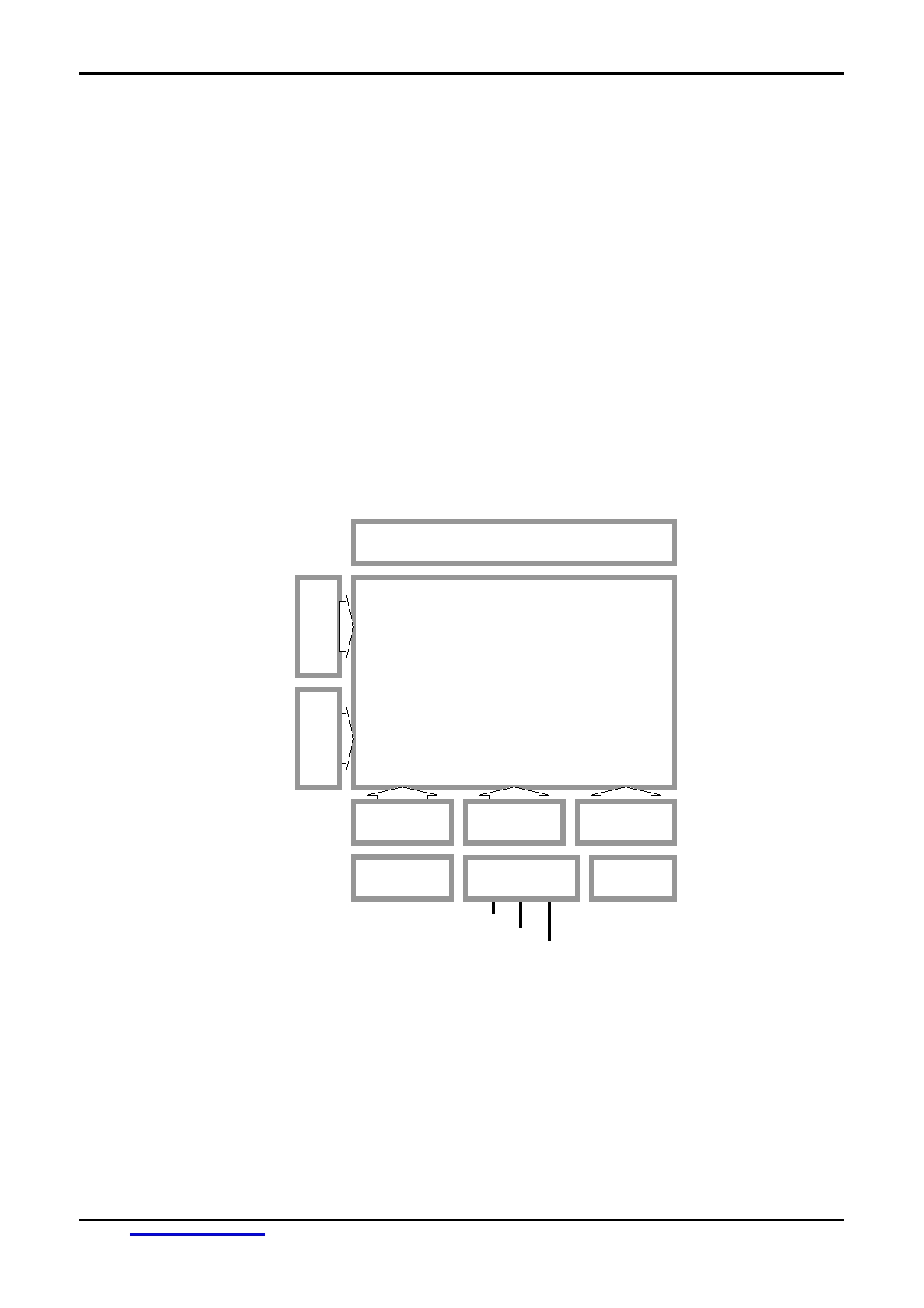
Block Diagram
BLA
LED Backlight Circuit
BLK
LCD Panel
240 x 128 pixels
SEGMENT
SEGMENT
SEGMENT
Driver
Driver
Driver
VDD, VSS, FG
Power and
T6963C
32k x 8bit
VOUT, V0
Booster Circuit
or equivalent
SRAM
DB0 - DB7
C/D, /RD, /WR
/CE, /RST, FS1
URL:
www.topwaydisplay.com
Document Name: LM240128TFW-Manual-Rev0.1.DOC
Page: 3 of 10
TOPWAY
LCD Module User Manual
LM240128TFW
1.4
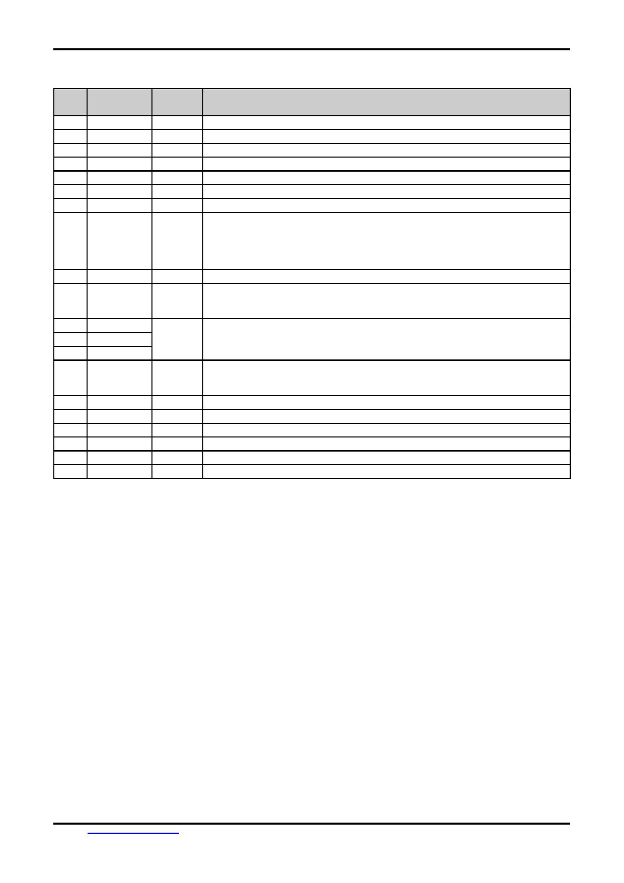
Terminal Functions
Pin
Pin
No.
Name
I/O
Descriptions
1
FG
Power
Frame Ground, Connected to VSS
2
VSS
Power
0V Power Supply, GND
3
VDD
Power
Positive Power Supply
4
V0
Power
LCD Contrast Reference Input
5
/WR
Input
Data or Command Write Signal
6
/RD
Input
Data or Status Read Signal
7
/CE
Input
Chip Enable Signal
8
C/D
Input
Address for Data or Command:
C/D=H, /WR=L, /RD=H : Command Write
C/D=H, /WR=H, /RD=L : Status Read
C/D=L, /WR=L, /RD=H : Data Write
C/D=L, /WR=H, /RD=L : Data Read
9
NC
-
No Connection, Leave Open
10
/RST
Input
Reset Signal:
/RST = L, Reset the LCD Module
/RST = H, Normal Running
11
DB0
I/O
8-bit data bus
:
:
18
DB7
19
FS1
Input
Font Selection Input:
FS1=H : 6x8 font
FS1=L : 8x8 font
20
VOUT
Power
Power Booster Output for V0
21
BLA
Power
Positive Power Supply for LED backlight
22
BLK
Power
Negative Power Supply for LED backlight
23
BLA
Power
Positive Power Supply for LED backlight
24
NC
-
No Connection, Leave Open
25
BLK
Power
Negative Power Supply for LED backlight
URL:
www.topwaydisplay.com
Document Name: LM240128TFW-Manual-Rev0.1.DOC
Page: 4 of 10
TOPWAY
LCD Module User Manual
LM240128TFW
2. Absolute Maximum Ratings
Items
Symbol
Min.
Max.
Unit
Condition
Supply Voltage
V DD
0
+6.0
V
V SS = 0V
Input Voltage
V IN
V SS -0.3
V DD +0.3
V
V SS = 0V
Operating Temperature
T OP
-20
+70
° C
No Condensation
Storage Temperature
T ST
-30
+80
° C
No Condensation
Cautions:
Any Stresses exceeding the Absolute Maximum Ratings may cause substantial damage to the device. Functional operation of this
device at other conditions beyond those listed in the specification is not implied and prolonged exposure to extreme conditions may
affect device reliability.
3. Electrical Characteristics
3.1
DC Characteristics
V SS =0V, V DD =5.0V, T OP =25 ° C
Items
Symbol
MIN.
TYP.
MAX.
Unit
Applicable Pin
Operating Voltage
V DD
4.5
5.0
5.5
V
VDD
DB0~DB8, /WR, /RD, /CE,
Input High Voltage
V IN
0.8xVDD
-
VDD
V
C/D, /RST, FS1
DB0~DB8, /WR, /RD, /CE,
Input Low Voltage
V IN
0
-
0.5
V
C/D, /RST, FS1
Operating Current
I DD
-
15.5
37.0
mA
VDD
3.2
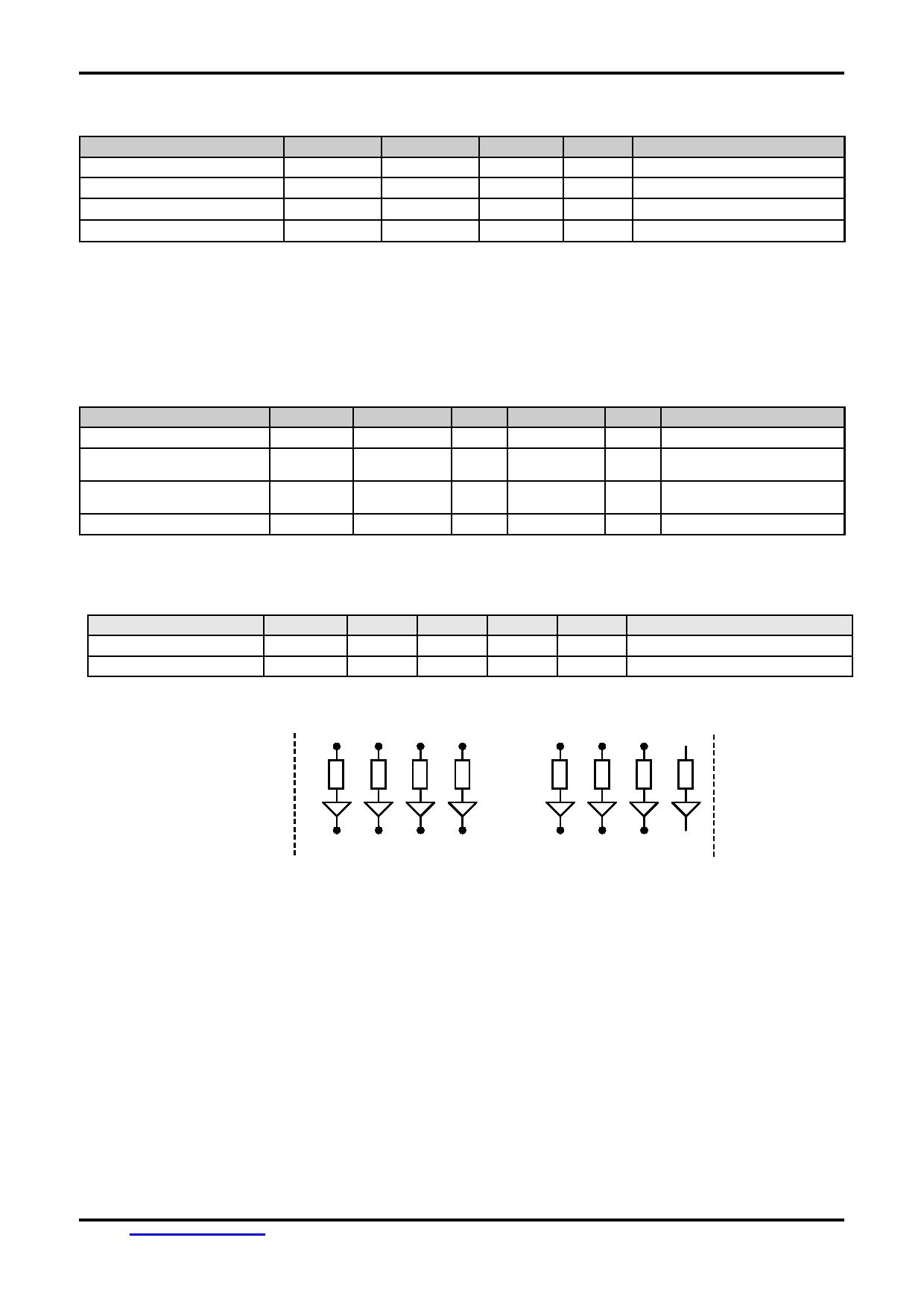
LED Backlight Circuit Characteristics
BLK=0V, If BLA =170mA, T OP =25 ° C
Items
Symbol
MIN.
TYP.
MAX.
Unit
Applicable Pin
Forward Voltage
Vf BLA
-
5.0
-
V
BLA
Forward Current
If BLA
-
170
200
mA
BLA
Cautions:
Exceeding the recommended driving current could cause substantial damage to the backlight and shorten its lifetime.
BLA
BLK
No. of LED = 10pcs
URL:
www.topwaydisplay.com
Document Name: LM240128TFW-Manual-Rev0.1.DOC
Page: 5 of 10
TOPWAY
LCD Module User Manual
LM240128TFW
3.3
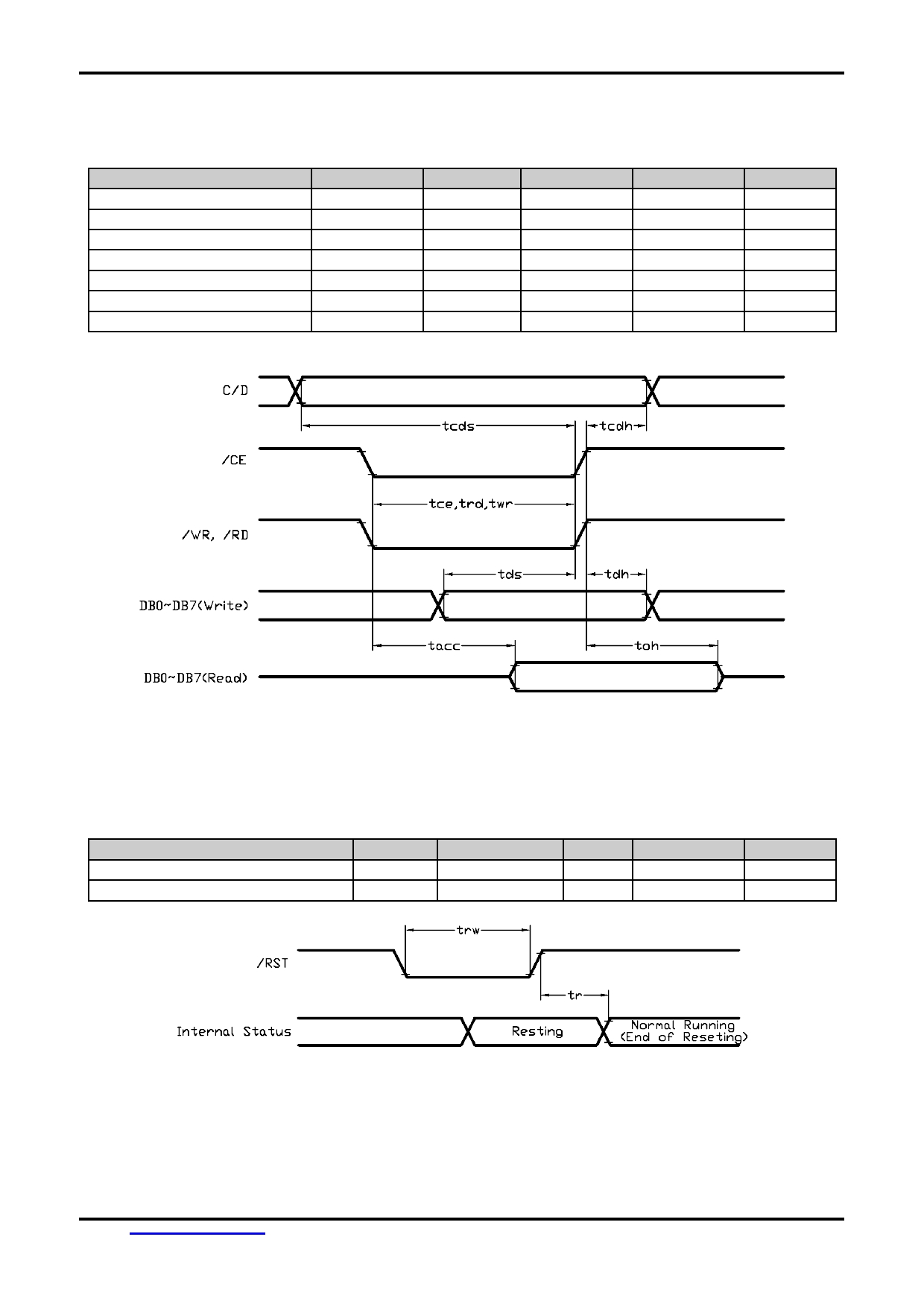
AC Characteristics
V SS =0V, V DD =5.0V, T OP =25 ° C
Item
Symbol
MIN.
TYP.
MAX.
Unit
C/D Setup Time
tcds
130
-
-
ns
C/D Hold Time
tcdh
13
-
-
ns
/CE,/RD,/WR Pulse Width
tce, trd, twr
100
-
-
ns
Data Setup Time
tds
100
-
-
ns
Data Hold Time
tdh
50
-
-
ns
Access Time
tacc
-
-
190
ns
Output Hold Time
toh
-
-
65
ns
Note: *1. Input signal rise/fall time should be less than 20ns
Bus Timing Diagram
3.3.1 Reset Timing
V SS =0V, V DD =5.0V, T OP =25 ° C
Item
Symbol
MIN.
TYP.
MAX.
Unit
Reset Time
tr
-
-
100
µs
Reset LOW pulse width
trw
100
-
-
µs
Reset Timing Diagram
URL:
www.topwaydisplay.com
Document Name: LM240128TFW-Manual-Rev0.1.DOC
Page: 6 of 10
TOPWAY
LCD Module User Manual
LM240128TFW
4. Function Specifications
4.1
Adjusting the Display Contrast
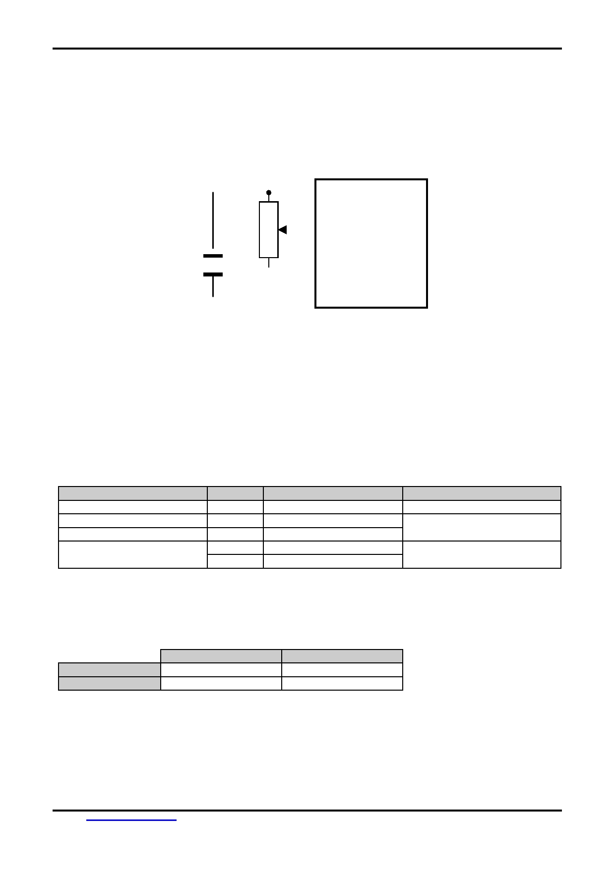
A Variable-Resistor must be connected to the LCD module for providing a reference to V0.
Adjusting the VR will result the change of LCD display contrast.
The recommended value of VR is 25k to 50k
LCD module
VDD
VR
V0
VOUT
VSS
4.2
Resetting the LCD module
The LCD module should be initialized by using /RST terminal.
While turning on the VDD and VSS power supply, maintain /RST terminal at LOW level. After the
power supply stabilized, release the reset terminal (/RST=HIGH)
4.3
Internal Hard-wired Setting
The followings are the major hard-wired setting of the T6963C in side the LCD module.
Items
Value
Wiring Setting
Note
Scanning Type
Single
/DUAL=H
Single scanning LCD
Logical Display Size (x)
320
MD3=H, MD2=L
Logical Display Size is NOT
Logical Display Size (y)
64
MDS=L, MD1=L, MD0=L
equal Physical Display Size
Font size setting
8x8 dot
FS0=L, FS1=L
Font size is depends on FS1
6x8 dot
FS0=L, FS1=H
status connected externally
4.4
Display Memory Mapping Parameter
Example:
Home Address
Area
Text Layer
0000(hex)
001E(hex)
Graphics Layer
0800(hex)
001E(hex)
Note:
*1.
For the details of the commands and T6963C operation please refer to T6963C Data sheet.
URL:
www.topwaydisplay.com
Document Name: LM240128TFW-Manual-Rev0.1.DOC
Page: 7 of 10
TOPWAY
LCD Module User Manual
LM240128TFW
4.5
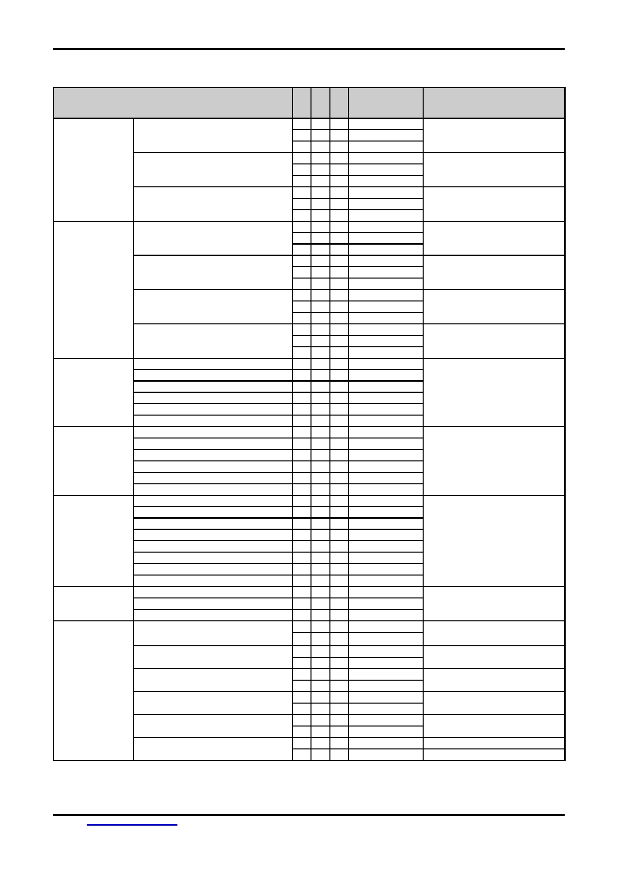
Commands Table
Command
Code (8bit)
Note
Registers
Set Cursor Pointer
0
1
0
X Address
Setting
0
1
0
Y Address
0
1
1
0010 0001
Set Offset Register
0
1
0
DATA
0
1
0
0000 0000
0
1
1
0010 0010
Set Address Pointer
0
1
0
Low Address
0
1
0
High Address
0
1
1
0010 0100
Set Control
Set Text Home Address
0
1
0
Low Address
Word
0
1
0
High Address
0
1
1
0100 0000
Set Text Area
0
1
0
Columns
0
1
0
0000 0000
0
1
1
0100 0001
Set Graphic Home Address
0
1
0
Low Address
0
1
0
High Address
0
1
1
0100 0010
Set Graphic Area
0
1
0
Columns
0
1
0
0000 0000
0
1
1
0100 0011
Mode Set
OR mode
0
1
1
1000 x000
EXOR mode
0
1
1
1000 x001
AND mode
0
1
1
1000 x011
Text Attribute mode
0
1
1
1000 x100
Internal CG ROM mode
0
1
1
1000 0xxx
External CG RAM mode
0
1
1
1000 1xxx
Display Mode
Display off
0
1
1
1001 0000
D3: Graphic Display on
Cursor on, Blink off
0
1
1
1001 xx10
D2: Text Display on
Cursor on, Blink on
0
1
1
1001 xx11
D1: Cursor Display on
Text on, Graphic off
0
1
1
1001 01xx
D0: Cursor Blink on
Text off, Graphic on
0
1
1
1001 10xx
Text on, Graphic on
0
1
1
1001 11xx
Cursor Pattern
1-line cursor
0
1
1
1010 0000
Select
2-line cursor
0
1
1
1010 0001
3-line cursor
0
1
1
1010 0010
4-line cursor
0
1
1
1010 0011
5-line cursor
0
1
1
1010 0100
6-line cursor
0
1
1
1010 0101
7-line cursor
0
1
1
1010 0110
8-line cursor
0
1
1
1010 0111
Data Auto
Set Data Auto Write
0
1
1
1011 0000
Read/Write
Set Data Auto Read
0
1
1
1011 0001
Auto Reset
0
1
1
1011 0010
Data
Data Write Increment ADP
0
1
0
Data
Read/Write
0
1
1
1100 0000
Data Read Increment ADP
0
1
1
1100 0001
1
0
0
Data
Data Write Decrement ADP
0
1
0
Data
0
1
1
1100 0010
Data Read Decrement ADP
0
1
1
1100 0011
1
0
0
Data
Data Write Non-variable ADP
0
1
0
Data
0
1
1
1100 0100
Data Read Non-variable ADP
0
1
1
1100 0101
1
0
0
Data
URL:
www.topwaydisplay.com
Document Name: LM240128TFW-Manual-Rev0.1.DOC
Page: 8 of 10
TOPWAY
LCD Module User Manual
LM240128TFW
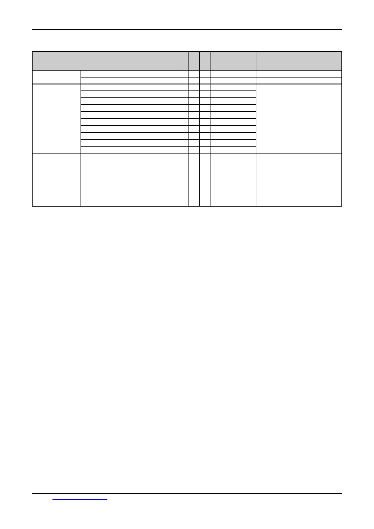
Commands Table (continue)
Command
Code (8bit)
Note
Screen
Screen Peek
0
1
1
1110 0000
Not use
Peek/Copy
Screen Copy
0
1
1
1110 1000
Not use
Bit Set/Reset
Bit Reset
0
1
1
1111 0xxx
D3: Set/Clear bit
Bit Set
0
1
1
1111 1xxx
D2,D1,D0: bit no.
Bit 0 (LSB)
0
1
1
1111 x000
Bit 1
0
1
1
1111 x001
Bit 2
0
1
1
1111 x010
Bit 3
0
1
1
1111 x011
Bit 4
0
1
1
1111 x100
Bit 5
0
1
1
1111 x101
Bit 6
0
1
1
1111 x110
Bit 7 (MSB)
0
1
1
1111 x111
Status Check
Check the status
1
0
1
Status
D0: Command execution ready
D1: Data read/write ready
D2: Auto mode data read ready
D3: Auto mode data write ready
D4: not used
D5: Controller operation normal
D6: Error Flag
D7: Normal display
Note:
*1. When sending commands or data, Status Check must be performed.
Otherwise, T6963C cannot operate normally, even after a delay time.
*2. For the details of the commands and T6963C operation please refer to T6963C Data sheet.
URL:
www.topwaydisplay.com
Document Name: LM240128TFW-Manual-Rev0.1.DOC
Page: 9 of 10

TOPWAY
LCD Module User Manual
LM240128TFW
5. Design and Handling Precaution
Please refer to "LCD-Module-Design-Handling-Precaution.pdf".
URL:
www.topwaydisplay.com
Document Name: LM240128TFW-Manual-Rev0.1.DOC
Page: 10 of 10