LM240160XCW
LCD Module User Manual
Prepared by:
Checked by:
Approved by:
ChenZhiGuo
Date: 2017-11-10
Date:
Date:
Rev. Descriptions
Release Date
0.1
Preliminary release
2017-11-10
URL: www.topwaydisplay.com
Document Name: LM240160XCW-Manual-Rev0.1
Page: 1 of 14

TOPWAY
LCD Module User Manual
LM240160XCW
Table of Content
1. Basic Specifications .............................................................................................................. 3
1.1
Display Specifications ............................................................................................................................................ 3
1.2
Mechanical Specifications ...................................................................................................................................... 3
1.3
Block Diagram ........................................................................................................................................................ 3
1.4
Terminal Functions ................................................................................................................................................. 4
Absolute Maximum Ratings ......................................................................................................... 5
2. Electrical Characteristics ...................................................................................................... 5
2.1
DC Characteristics ................................................................................................................................................. 5
2.2
LED Backlight Circuit Characteristics ..................................................................................................................... 5
2.3
AC Characteristics ................................................................................................................................................. 6
2.4
Reset Timing .......................................................................................................................................................... 9
3. Function Specifications ...................................................................................................... 10
3.1
Application circuit(Example) ................................................................................................................................. 10
3.2
Adjusting the Display Contrast ............................................................................................................................. 10
3.3
Resetting the LCD module ................................................................................................................................... 10
3.4
Display Memory Map ........................................................................................................................................... 11
3.5
Command Table ................................................................................................................................................... 12
4. Design and Handling Precaution ........................................................................................ 14
URL: www.topwaydisplay.com
Document Name: LM240160XCW-Manual-Rev0.1
Page: 2 of 14
TOPWAY
LCD Module User Manual
LM240160XCW
1. Basic Specifications
1.1 Display Specifications
1) LCD Display Mode
: FSTN, Positive, Transflective
2) Display Color
: Display Data = “1” : Dark Gray (*1)
: Display Data = “0” : Light Gray (*2)
3) Viewing Angle
: 6H
4) Driving Method
: 1/160 duty, 1/12 bias
5) Back Light
: White LED backlight
Note:
*1. Color tone may slightly change by Temperature and Driving Condition.
*2. The Color is defined as the inactive / background color
*3. Fine Contrast adjustment function is necessary in the application design for optimal display result
1.2 Mechanical Specifications
1) Outline Dimension
: 85.1 x 61.6 x 9.5 MAX(exclude FPC)
(See attached Outline Drawing for details)
1.3 Block Diagram
LCD Panel
240 x 160 pixels
D0~D7
IF1 , IF2 , IF3 , /CS./RST,A0,/WR,/RD
ST7586S
VDDA,VDD,VM,V0,XVO,VG
or
VSS,ESD
equivalent
BLK
Back Light Circuit
BLA
URL: www.topwaydisplay.com
Document Name: LM240160XCW-Manual-Rev0.1
Page: 3 of 14
TOPWAY
LCD Module User Manual
LM240160XCW
1.4 Terminal Functions
Descriptions
Pin No.
Pin Name
I/O
8080 mode
4-SPI
3-SPI
( default )
6800 mode
mode
mode
1
ESD
Power Connected Ground
2
ESD
Power Connected Ground
Register Select
A0(SCL)
Input RS=HIGH: data on DB0 to DB7 is display data
Serial clock input
3
RS=LOW: data on DB0 to DB7 is control data
/WR=L H, /RD=H;
R/W=H,E=H;
Not used,
Data or Instruction
Data or Status connect to VDD
4
/WR(R/W)
Input
latch into the LCD
read from the LCD
module
module
R/W=L,E=H L;
Data or Status
latch into the LCD
module
5
D0(SDA)
I/O
8-bit Data bus;
Serial data input
6
D1(A0)
Three state I/O terminal for display data or
Not used,
instruction data
Register Select
A0=HIGH:
connect
when /CS=H, D0~D7=High Impedance
Transferring
to VDD
the Display Data
A0=LOW:
Transferring
the Control Data
7
D2
Not used,
...
…
connect to VDD
12
D7
/WR=H, /RD=L;
R/W=H,E=H;
Not used,
Data or Status read
Data or Status connect to VDD
13
/RD (E)
Input
form the LCD module
read from the LCD
module
R/W=L,E=H L;
Data or Status
latch into the LCD
module
14
/RST
Input Reset input pin. When /RST is “L”, internal initialization procedure is executed.
15
IF1
These pins select interface operation mode.
IF1=L, IF2=H, IF3=H 80 series 8-bit parallel
IF2
Input IF1=L, IF2=L, IF3=H 68 series 8-bit parallel
IF1=H, IF2=H, IF3=L 8-bit serial (4-Line)
17
IF3
IF1=L, IF2=H, IF3=L 9-bit serial (3-Line)
Note: Refer to “Interface Selection” for detailed information.
Chip select input pin.
18
/CS
Input /CS =“L”: This chip is selected and the MPU interface is active.
/CS =“H”: This chip is not selected and the MPU interface is disabled (D[7:0] are high
impedance).
19
VDD
Power Power Supply
20
VDD
Power Power Supply
21
VSS
Power 0V Supply, Ground (0V)
22
VDDA
Power Power Supply
23
VM
Power VM is the non-select voltage level of COM-drivers
24
V0
Power Positive operating voltage of COM-drivers.
25
XV0
Power Negative operating voltage of COM-drivers.
26
VG
Power VG is the power of SEG-drivers
27
ESD
Power Connected Ground
28
ESD
Power Connected Ground
URL: www.topwaydisplay.com
Document Name: LM240160XCW-Manual-Rev0.1
Page: 4 of 14

TOPWAY
LCD Module User Manual
LM240160XCW
Absolute Maximum Ratings
Items
Symbol
Min.
Max.
Unit Condition
Supply Voltage
V DD
-0.3
+3.6
V
V SS = 0V
Input Voltage
V IN
-0.3
V DD +0.3
V
V SS = 0V
Operating Temperature
T OP
-20
+70
C
No Condensation
Storage Temperature
T ST
-30
+80
C
No Condensation
Cautions:
Any Stresses exceeding the Absolute Maximum Ratings may cause substantial damage to the device. Functional
operation of this device at other conditions beyond those listed in the specification is not implied and prolonged exposure
to extreme conditions may affect device reliability.
2. Electrical Characteristics
2.1 DC Characteristics
V SS =0V, V DD =3.3V, T OP =25 C
Items
Symbol
MIN.
TYP
MAX.
Unit Condition /
.
Application Pin
Operating Voltage
V DD
3.0
3.3
3.4
V
VDD
Input High Voltage
V IH
0.8xV DD
-
V DD
V
/RST, /CS, A0, /WR, /RD,
Input Low Voltage
V IL
0
-
0.2xV DD
V
DB0~DB7
Operating Current
I DD
-
1.06
2.65
mA VDD
2.2 LED Backlight Circuit Characteristics
BLK=0V,BLA=3.3V ,T OP =25 C
Items
Symbol
MIN.
TYP.
MAX.
Unit Applicable Pin
Forward Voltage
BLA
-
3.3
-
V
BLA
Forward Current
I BLA
-
76
100
mA BLA
Cautions:
Exceeding the recommended driving current could cause substantial damage to the backlight and shorten its lifetime.
BLA
BLK
No. of LED = 5pcs
URL: www.topwaydisplay.com
Document Name: LM240160XCW-Manual-Rev0.1
Page: 5 of 14
TOPWAY
LCD Module User Manual
LM240160XCW
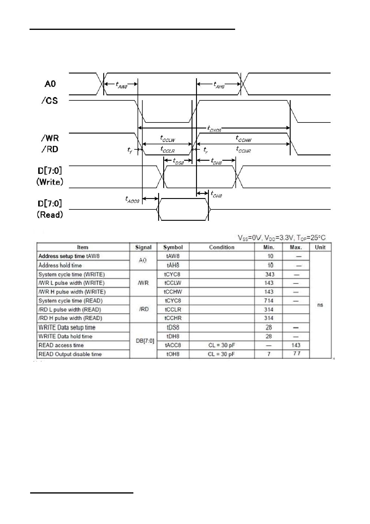
2.3 AC Characteristics
2.3.1 8080 Mode System Bus Timing
Note:
1. The input signal rise time and fall time (tr, tf) is specified at 10 ns or less.
2. Please refer to ST7586S data sheet for details.
URL: www.topwaydisplay.com
Document Name: LM240160XCW-Manual-Rev0.1
Page: 6 of 14

TOPWAY
LCD Module User Manual
LM240160XCW
2.3.2 6800 Mode System Bus Timing
Note:
1. The input signal rise time and fall time (tr, tf) is specified at 10 ns or less.
2. Please refer to ST7586S data sheet for details.
URL: www.topwaydisplay.com
Document Name: LM240160XCW-Manual-Rev0.1
Page: 7 of 14
TOPWAY
LCD Module User Manual
LM240160XCW
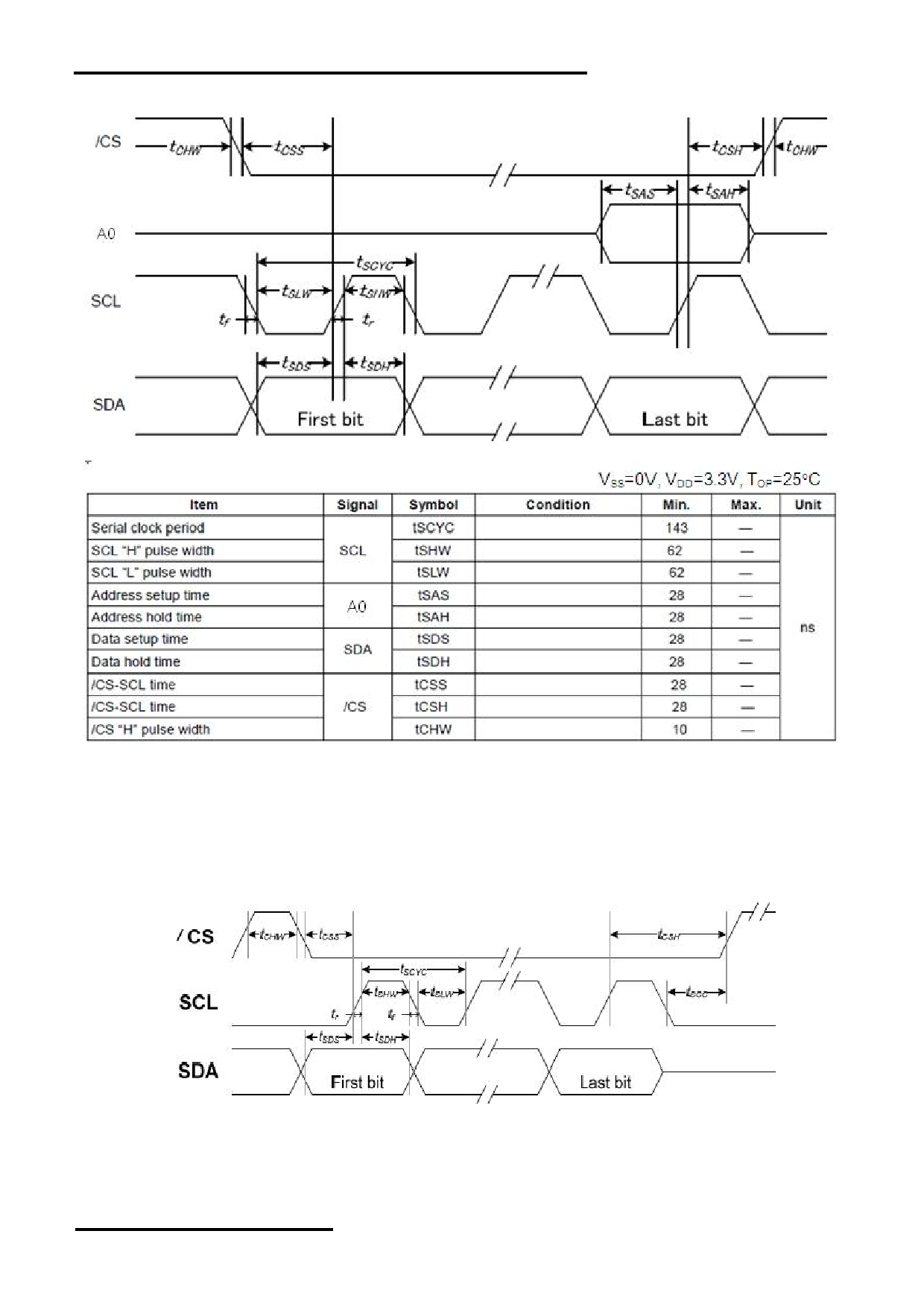
2.3.3 SPI Mode System Bus Timing( 4-Line )
Note:
1. The input signal rise and fall time (tr, tf) are specified at 10 ns or less.
2. Please refer to ST7586S data sheet for details.
2.3.4 SPI Mode System Bus Timing( 3-Line )
URL: www.topwaydisplay.com
Document Name: LM240160XCW-Manual-Rev0.1
Page: 8 of 14
TOPWAY
LCD Module User Manual
LM240160XCW
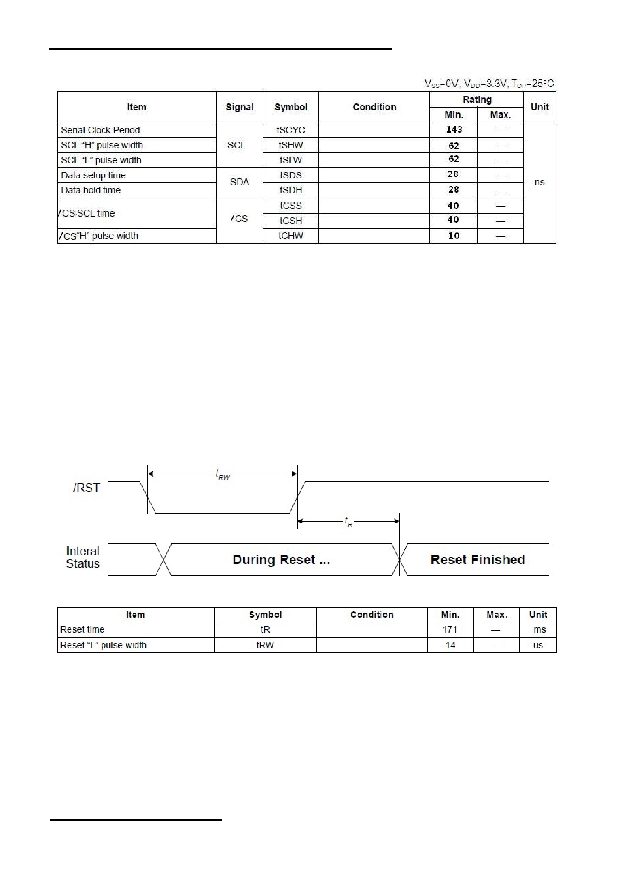
Note:
1. The input signal rise and fall time (tr, tf) are specified at 15 ns or less.
2. All timing is specified using 20% and 80% of VDD as the standard.
2.4 Reset Timing
VSS=0V,VDD=3.3V,Ta= 25 C
URL: www.topwaydisplay.com
Document Name: LM240160XCW-Manual-Rev0.1
Page: 9 of 14
TOPWAY
LCD Module User Manual
LM240160XCW
3. Function Specifications
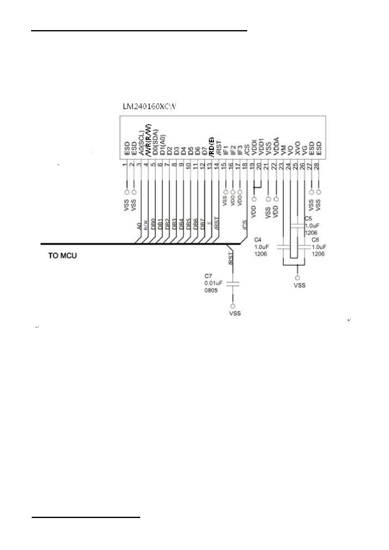
3.1 Application circuit(Example)
- Internal Boosting
- 8080 mode
Note:
Please refer to the ST7586 data sheet for details
3.2 Adjusting the Display Contrast
- This LCD module equipped with latest digital contrast adjustment function.
- Its display contrast could be adjusted by MCU command. (please see the command tables for details)
- It is recommended to provide a contrast adjustment interface for end-user, where the best display result
could meet the individual preference in mass production.
3.3 Resetting the LCD module
The LCD module should be initialized by using /RST terminal.
While turning on the VDD and VSS power supply, maintain /RST terminal at LOW level.
After the power supply stabilized, release the reset terminal (/RST=HIGH)
URL: www.topwaydisplay.com
Document Name: LM240160XCW-Manual-Rev0.1
Page: 10 of 14
TOPWAY
LCD Module User Manual
LM240160XCW
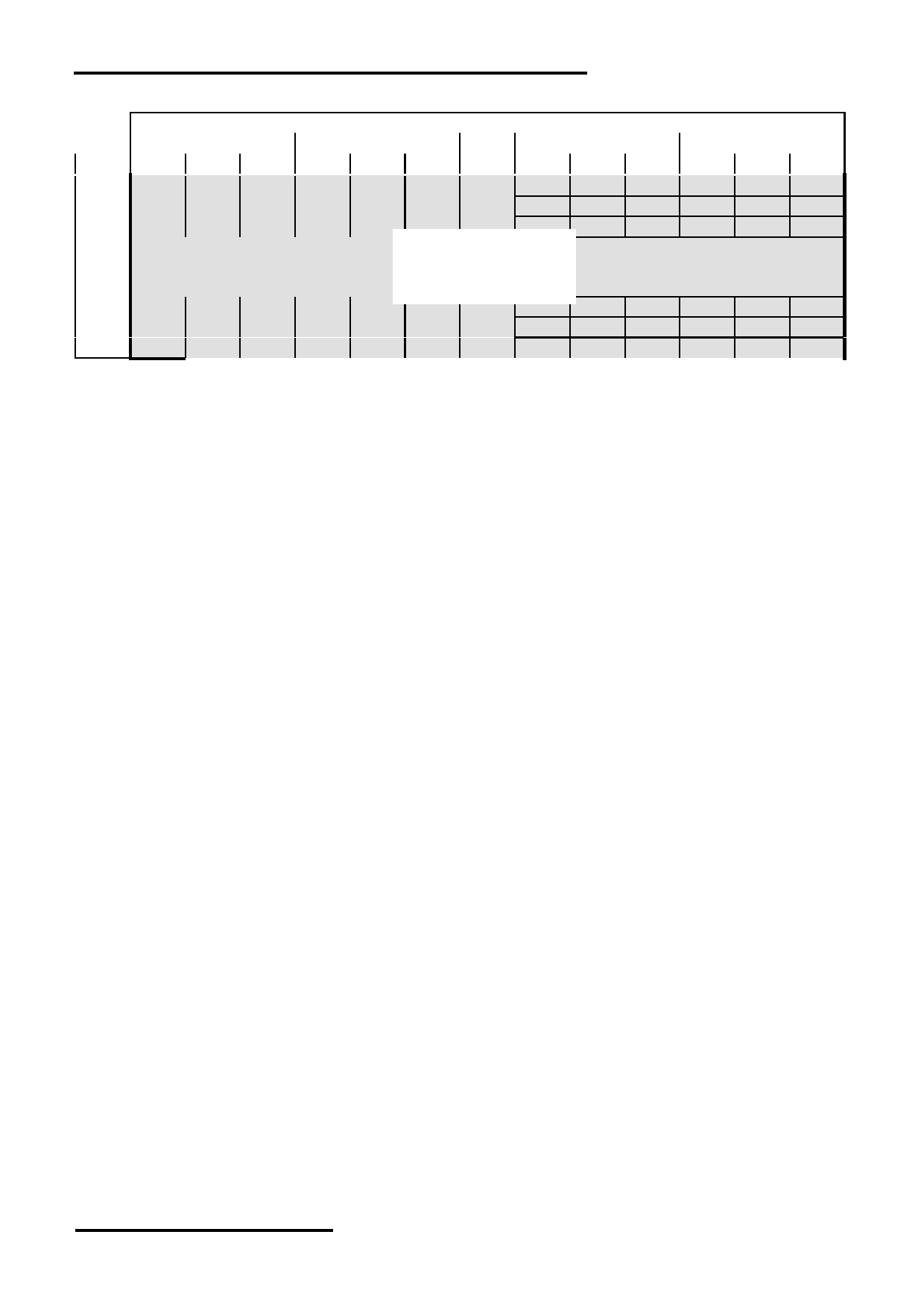
3.4 Display Memory Map
Column Add (dec)
0
1
…
78
79
LINE D7, D6 D4, D3 D1, D0 D7, D6 D4, D3 D1, D0
D7, D6
D4, D3
D1, D0
D7, D6
D4, D3
D1, D0
0
1
2
:
:
240x160dot
:
157
158
159
Pixel mapping (Top View)
Note:
*1. Based on the top view of the LCD module
*2. The above is memory map based on:
MX[1:0]=11 , MY=1
Inverse Display = Normal
All Pixel ON/OFF =OFF
Display ON/OFF = ON
Partial Mode = OFF
Start Line =0
Display Mode = Monochrome mode
Display Duty = 1/160
*3. 1Byte data in Column Add relate to 3 pixels
*4. D7D6/D4D3/D1D0=11, on dot ; D7D6/D4D3/D1D0=00, off dot ; D5,D2 has no function
*5. please refer to ST7586s datasheet for details and gray scale operation
URL: www.topwaydisplay.com
Document Name: LM240160XCW-Manual-Rev0.1
Page: 11 of 14
TOPWAY
LCD Module User Manual
LM240160XCW
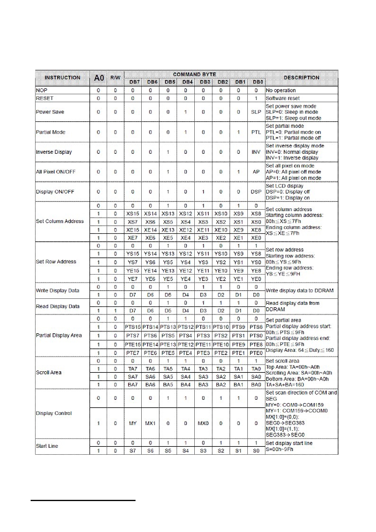
3.5 Command Table
The following setting should be issue to LCD module after hardware reset.
URL: www.topwaydisplay.com
Document Name: LM240160XCW-Manual-Rev0.1
Page: 12 of 14
TOPWAY
LCD Module User Manual
LM240160XCW
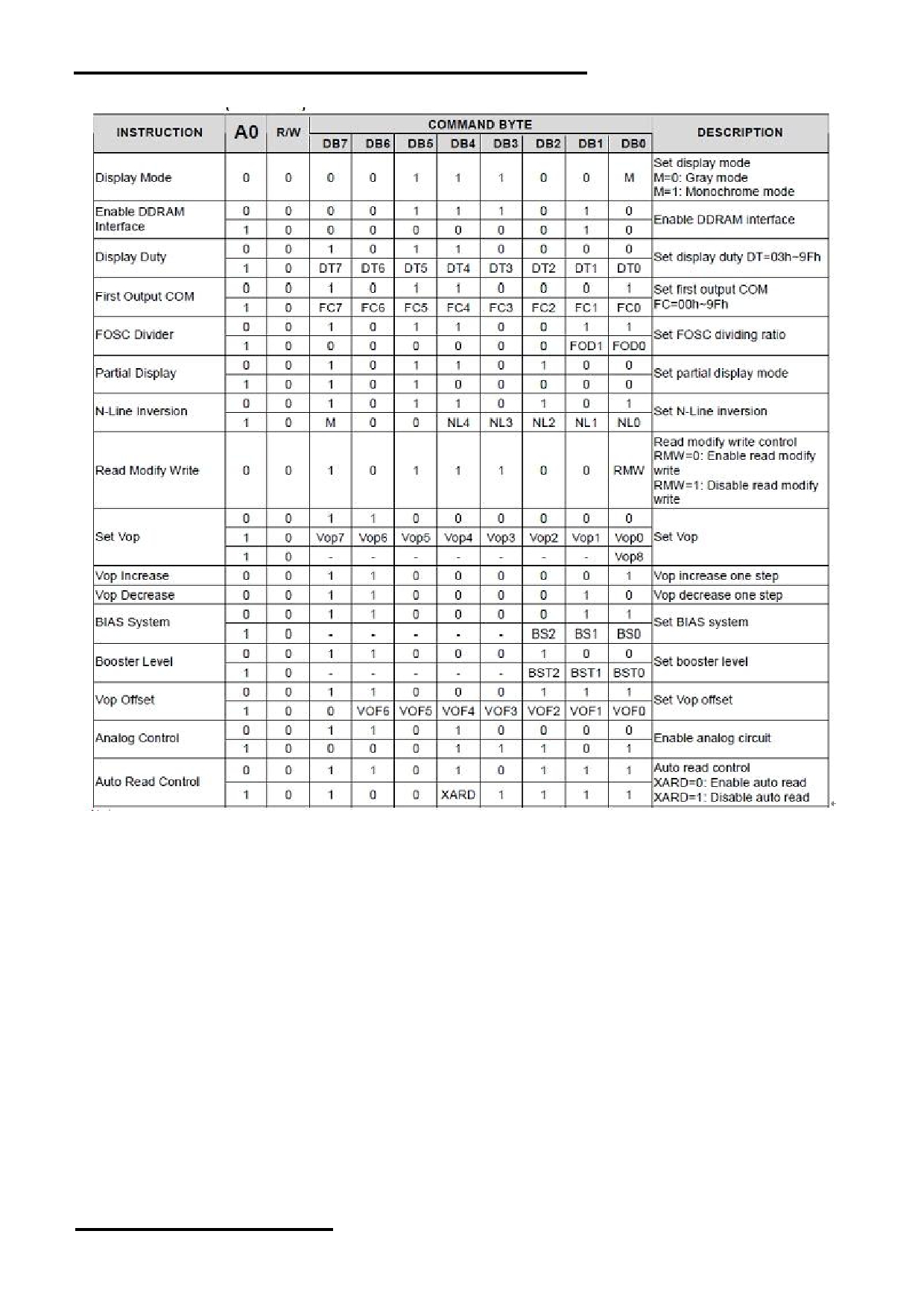
Command Table (continue)
Note:
Please refer to ST7586S data sheet for details
R/W=0 means it is a write function, R/W=1 means it is a read function
A0=0 means it is a control data, A0=1 means it is a display data
URL: www.topwaydisplay.com
Document Name: LM240160XCW-Manual-Rev0.1
Page: 13 of 14

TOPWAY
LCD Module User Manual
LM240160XCW
4. Design and Handling Precaution
Please refer to "LCD-Module-Design-Handling-Precaution.pdf".
URL: www.topwaydisplay.com
Document Name: LM240160XCW-Manual-Rev0.1
Page: 14 of 14