LM6020FCW-2
LCD Module User Manual
Prepared by:
Checked by:
Approved by:
Li KeKe
Date: 2020-11-26
Date:
Date:
Rev. Descriptions
Release Date
0.1
New release
2020-11-26
URL: www.topwaydisplay.com
Document Name: LM6020FCW-2-Manual-Rev0.1.DOC
Page: 1 of 14

TOPWAY
LCD Module User Manual
LM6020FCW-2
Table of Content
1. Basic Specifications ................................................................................................................................ 3
1.1 Display Specifications ......................................................................................................................................................................... 3
1.2 Mechanical Specifications ................................................................................................................................................................. 3
1.3 Block Diagram ...................................................................................................................................................................................... 3
1.4 Terminal Functions ............................................................................................................................................................................ 4
2. Absolute Maximum Ratings ................................................................................................................... 5
3. Electrical Characteristics ....................................................................................................................... 5
3.1 DC Characteristics ............................................................................................................................................................................. 5
3.2 LED Backlight Circuit Characteristics ............................................................................................................................................. 5
3.3 AC Characteristics .............................................................................................................................................................................. 6
4. Function specifications ........................................................................................................................ 10
4.1 Application circuit(Example) ............................................................................................................................................................ 10
4.2 Adjusting the Display Contrast ........................................................................................................................................................ 10
4.3 Basic Setting ...................................................................................................................................................................................... 10
4.4 Resetting the LCD module .............................................................................................................................................................. 10
4.5 Display Memory Map ........................................................................................................................................................................ 11
4.6 Display Commands ........................................................................................................................................................................... 12
5. Design and Handling Precaution ....................................................................................................... 14
URL: www.topwaydisplay.com
Document Name: LM6020FCW-2-Manual-Rev0.1.DOC
Page: 2 of 14
TOPWAY
LCD Module User Manual
LM6020FCW-2
1. Basic Specifications
1.1 Display Specifications
1) LCD Display Mode
: FSTN, Positive, Transflective
2) Display Color
: Display Data = “1” : Dark Gray(*1)
: Display Data = “0” : Light Gray (*2)
3) Viewing Angle
: 6H
4) Driving Method
: 1/65 duty, 1/10 bias
5) Backlight
: White LED backlight
Note:
*1. Color tone may slightly change by Temperature and Driving Condition.
*2. The Color is defined as the inactive / background color
*3. Fine Contrast adjustment function is necessary in the application design for optimal display result
1.2 Mechanical Specifications
1) Outline Dimension
: 44.9x 32.6 x 8.9MAX (mm)
(See attached Outline Drawing for details)
1.3 Block Diagram
BLA
Backlight Circuit
BLK
LCD Panel
128×64Pixels
VDD
VSS
UC1628c or equivalent
CD,/CS1, RESET,WR0,WR1 ,
VLCD,VB0-,VB0+,VB1-,VB1+,
BM0,BM1,
URL: www.topwaydisplay.com
Document Name: LM6020FCW-2-Manual-Rev0.1.DOC
Page: 3 of 14

TOPWAY
LCD Module User Manual
LM6020FCW-2
1.4 Terminal Functions
Descriptions
PIN
8080 mode
Pin No.
Name
I/O
(default )
6800 mode
4-SPI mode I2C mode
1
Chip Select
Not used,
/CS1
I
/CS=L, enable access to the LCD module
connect to VSS
/CS=H, disable access to the LCD module
2
Reset signal
RESET
I
/RES = L, Initialization is executed
/RES = H, Normal running.
3
Register Select
Not used,
CD
I
D/C = H, Transferring the Display Data
connect to VSS
D/C = L, Transferring the Control Data
WR0=L H,
WR0=H,WR1=
Not used,
Not used,
4
WR1=H;
H;
connect to
connect to VSS
WR0
I
Data or
Data or Status VSS
Instruction
read from the
latch into the
LCD module
LCD module
WR0=L,WR1=H
5
WR0=L H,
L;
WR1=H;
Data or Status
latch into the
WR1
I
Data or
Instruction
LCD module
latch into the
LCD module
6
D0
8-bit Data bus;
In serial modes, connect D[0] to
:
:
I/O
Three state I/O terminal for
SCK, D[3] to SDAI for write and
13
display data or instruction data
D[5:4] to SDAO for read.
when /CS=H, D0~D7=High
SDAI and SDAO may be
D7
Impedance.
connected together if necessary.
Connect unused pins to VSS.
14
VDD
P
Positive power supply
15
VSS
P
Negative power supply,0V
16,17
NC
-
-
18
VB0-
LCD Bias Voltages. These are the voltage sources to provide SEG d
19
VB0+
P
riving currents.
20
VB1-
21
VB1+
22~27
NC
-
-
28
VLCD
P
High voltage LCD Power Supply
29
NC
-
-
30
BM0
Bus mode;The interface bus mode is determined by BM[1:0]:
31
Mode
BM[1;0]
I
8080(8-bit)
10
BM1
6800(8-bit)
11
4-wire SPI w/ 8-bit token (S8)
01
2-wire SPI(I ² C)
00
32
NC
-
-
URL: www.topwaydisplay.com
Document Name: LM6020FCW-2-Manual-Rev0.1.DOC
Page: 4 of 14

TOPWAY
LCD Module User Manual
LM6020FCW-2
2. Absolute Maximum Ratings
Items
Symbol
Min.
Max.
Unit Condition
Supply Voltage
V DD
-0.3
+4.0
V
V SS = 0V
Input Voltage
V IN
-0.3
+4.0
V
V SS = 0V
Operating Temperature
T OP
-40
+70
C
No Condensation
Storage Temperature
T ST
-40
+80
C
No Condensation
Cautions:
Any Stresses exceeding the Absolute Maximum Ratings may cause substantial damage to the device. Functional
operation of this device at other conditions beyond those listed in the specification is not implied and prolonged exposure
to extreme conditions may affect device reliability.
3. Electrical Characteristics
3.1 DC Characteristics
V SS =0V, V DD =3.3V, T OP =25 C
Items
Symbol
MIN.
TYP.
MAX.
Unit Condition /
Application Pin
Operating Voltage
V DD
3.0
3.3
3.6
V
VDD
Input High Voltage
V IH
0.8xV DD
-
V DD
V
REST, /CS1,
Input Low Voltage
V IL
V SS
-
0.2xV DD
V
D0~D7,CD,WR0,W
R1,BM0,BM1
Operating Current
I DD
-
0.4
1.45
mA VDD
3.2 LED Backlight Circuit Characteristics
VSS=0V,BLA=3.3V, T OP =25 C
Items
Symbol
MIN.
TYP.
MAX.
Unit
Applicable Pin
Forward Voltage
V BLA
-
3.3
-
V
BLA
Forward Current
I BLA
-
34
40
mA
BLA
Cautions:
Exceeding the recommended driving current could cause substantial damage to the backlight and shorten its lifetime.
BLA
VSS
No. of LED = 2pcs
URL: www.topwaydisplay.com
Document Name: LM6020FCW-2-Manual-Rev0.1.DOC
Page: 5 of 14

TOPWAY
LCD Module User Manual
LM6020FCW-2
3.3 AC Characteristics
3.3.1 8080 Mode System Bus Timing
V DD =3.3V V SS =0V, T OP =25 C
Item
Symbol
MIN.
MAX.
Unit
Address setup time (CD)
tas80
20
-
ns
Address hold time (CD)
tah80
26
-
ns
System cycle time (read)
tcy80
560
-
ns
System cycle time(write)
tcy80
364
-
ns
Read pulse width
tpwr80
260
-
ns
Write pulse width
tpww80
163
-
ns
High pulse width (read)
thpw80
260
-
ns
High pulse width (write)
thpw80
163
-
ns
Data setup time
tds80
59
-
ns
Data hold time
tdh80
13
-
ns
Data access time
tacc80
-
260
ns
Data output disable time
tod80
70
ns
Chip select setup time
tcssa80
7
-
ns
Chip select hold time
tcsh80
7
-
ns
Note:
*1. Input signal rise/fall time should be less than 15ns .
*2. CL=100pF
*3.All timing is using 20% and 80% of VDD as the reference.
URL: www.topwaydisplay.com
Document Name: LM6020FCW-2-Manual-Rev0.1.DOC
Page: 6 of 14
TOPWAY
LCD Module User Manual
LM6020FCW-2
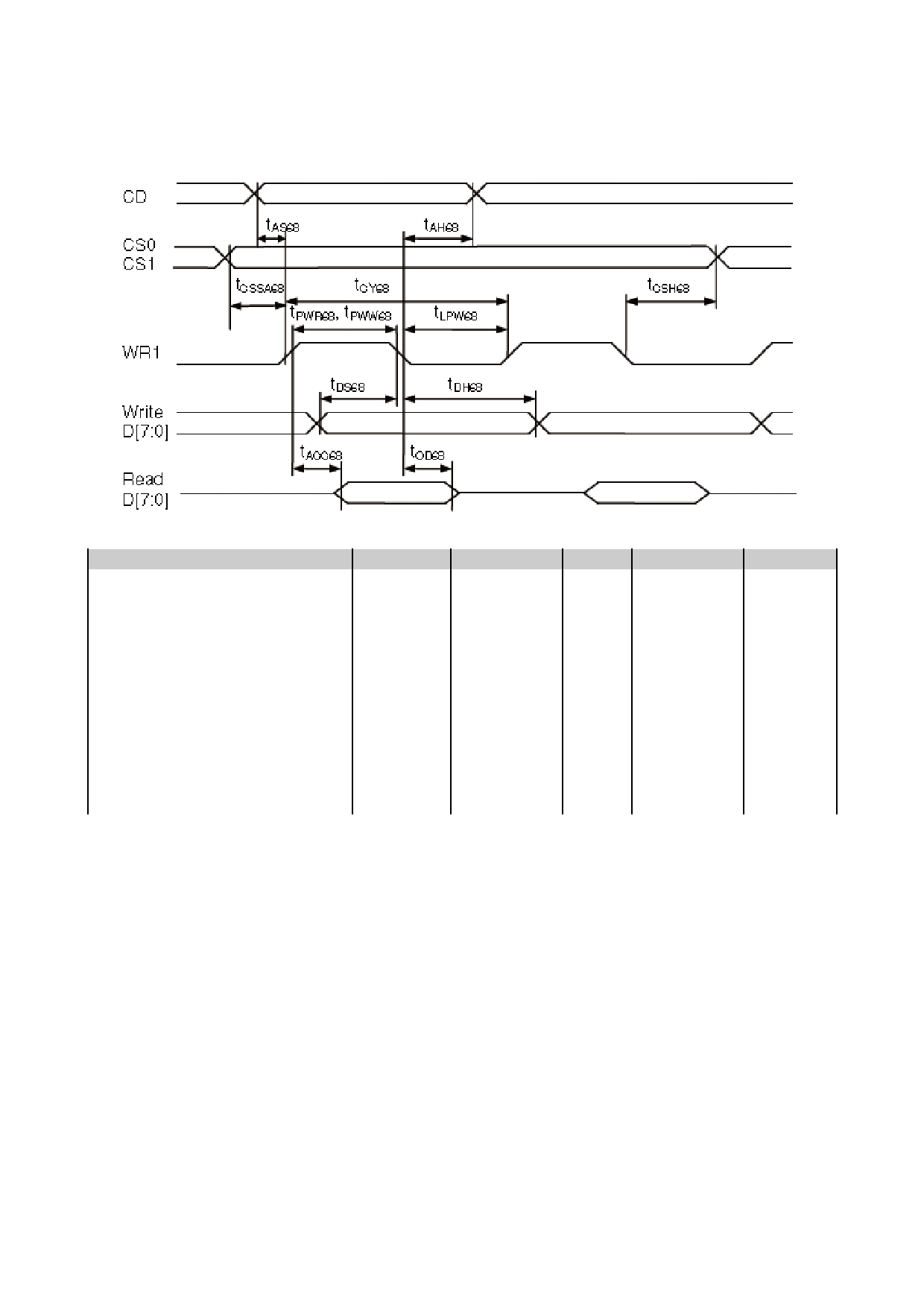
3.3.2 6800 Mode System Bus Timing
V SS =0V, V DD =3.3V, T OP =25 C
Item
Symbol
MIN.
TYP.
MAX.
Unit
Address setup time
tAS68
15
-
-
ns
Address hold time
tAH68
20
-
-
ns
System cycle time(WRITE)
tCY68
280
-
-
ns
/WR L pulse width(WRITE)
tLPW68
125
-
-
ns
/WR H pulse width(WRITE)
tPWW68
125
-
-
ns
System cycle time(READ)
tCY68
430
-
-
ns
/RD L pulse width(READ)
tLPW68
200
-
-
ns
/RD H pulse width(READ)
tPWR
200
-
-
ns
WRITE Data setup time
tDS68
45
-
-
ns
WRITE Data hold time
tDH68
10
-
-
ns
READ access time
tACC68
-
-
200
ns
READ Output disable time
tOD68
100
-
-
ns
Note:
*1. Input signal rise/fall time should be less than 15ns .
*2. CL=100pF
*3.All timing is using 20% and 80% of VDD as the reference.
URL: www.topwaydisplay.com
Document Name: LM6020FCW-2-Manual-Rev0.1.DOC
Page: 7 of 14
TOPWAY
LCD Module User Manual
LM6020FCW-2
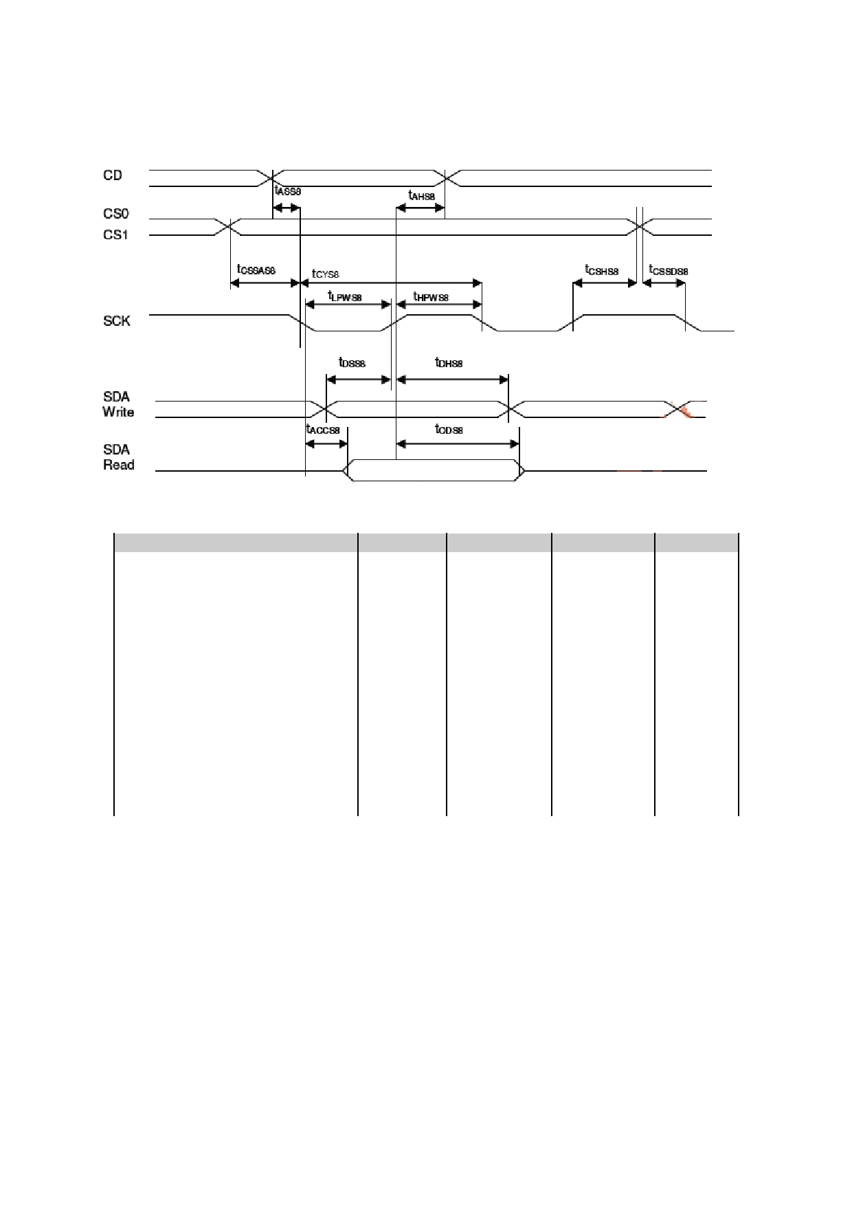
3.3.3 4-wire SPI w/ 8-bit token (S8)
V DD =3.3V V SS =0V, T OP =25 C
Item
Symbol
MIN.
MAX.
Unit
Address setup time (CD)
Tass8
0
-
ns
Address hold time (CD)
TAHs8
20
-
ns
System cycle time (read)
Tcys8
559
-
ns
System cycle time (write)
Tcys8
286
-
ns
Low pulse width(read)
tLPWS8
260
-
ns
Low pulse width(write)
tLPWS8
124
-
ns
High pulse width (read)
Thpws8
260
-
ns
High pulse width (write)
Thpws8
124
-
ns
Data setup time
Tdss8
33
-
ns
Data hold time
Tdhs8
20
-
ns
Data access time
Taccs8
-
260
ns
Data output disable time
Tods8
21
ns
Chip select setup time
tCSSAs8
7
-
ns
Chip select hold time
tCSHs8
20
-
ns
Note:
*1. Input signal rise/fall time should be less than 15ns .
*2. CL=100pF
*3.All timing is using 20% and 80% of VDD as the reference.
URL: www.topwaydisplay.com
Document Name: LM6020FCW-2-Manual-Rev0.1.DOC
Page: 8 of 14

TOPWAY
LCD Module User Manual
LM6020FCW-2
3.3.4 I2C Mode System Bus Timing
V DD =3.3V V SS =0V, T OP =25 C
Item
Symbol
MIN.
MAX.
Unit
SCK cycle time(read)
tCYI2C
689
-
ns
SCK cycle time(write)
tCYI2C
299
-
ns
Low pulse width(read)
tLPWI2C
325
-
ns
Low pulse width(write)
tLPWI2C
130
-
ns
High pulse width(read)
tHPWI2C
325
-
ns
High pulse width(write)
tHPWI2C
130
-
ns
Rise time and fall time
tr, tf
-
-
ns
Data setup time
tSSDAI2C
72
-
ns
Data hold time
tHDAI2C
13
-
ns
START Setup time
tSSTAI2C
13
-
ns
START Hold time
tHSTAI2C
72
-
ns
STOP setup time
tSSTOI2C
13
-
ns
Bus Free time between
STOP and START condition
tBUF
98
-
ns
Note:
*1. Input signal rise/fall time should be less than 15ns .
*2. CL=100pF
*3.All timing is using 20% and 80% of VDD as the reference.
3.3.5 Reset Timing
V SS =0V, V DD =3.3V, T OP =25 C
Item
Symbol
MIN.
TYP.
MAX.
Unit
Reset time
tr
4
-
-
μs
Reset LOW pulse width
trw
150
-
-
ms
Note:
*1.All timing is using 20% and 80% of VDD as the reference.
URL: www.topwaydisplay.com
Document Name: LM6020FCW-2-Manual-Rev0.1.DOC
Page: 9 of 14

TOPWAY
LCD Module User Manual
LM6020FCW-2
4. Function specifications
4.1 Application circuit(Example)
4.2 Adjusting the Display Contrast
-This LCD module equipped with latest digital contrast adjustment function.
-Its display contrast could be adjusted by MCU command. (please see the command tables for
details)
-It is recommended to provide a contrast adjustment interface for end-user, where the best display
result could meet the individual preference in mass production.
4.3 Basic Setting
To drive the LCD module correctly and provide normally display, please use the following setting
- Set Bias 1/10
- Set Duty 1/65
- MY = 1, MX =0
- AP=0 (Normal display)
- Analog SET
- Power control
- Display ON
Note:
*1. These setting/commands should issue the LCD module while start up.
*2. See the Display Commands section for details.
4.4 Resetting the LCD module
The LCD module should be initialized by using /RES terminal.
While turning on the VDD and VSS power supply, maintain /RES terminal at LOW level. After the
power supply stabilized, release the reset terminal (/RES=HIGH)
URL: www.topwaydisplay.com
Document Name: LM6020FCW-2-Manual-Rev0.1.DOC
Page: 10 of 14

TOPWAY
LCD Module User Manual
LM6020FCW-2
4.5 Display Memory Map
Page address
data
LCD Display (front view)
D7
0
:
D0
D7
1
:
D0
D7
2
:
D0
D7
3
:
D0
D7
4
:
128x64 pixels
D0
D7
5
:
D0
D7
6
:
D0
D7
7
:
D0
Column Address
00h
7Fh
Note:
*1.MY=1
*2.MX=0
*3.Initial Display Line=0
URL: www.topwaydisplay.com
Document Name: LM6020FCW-2-Manual-Rev0.1.DOC
Page: 11 of 14

TOPWAY
LCD Module User Manual
LM6020FCW-2
4.6 Display Commands
The following is a list of host commands supported by UC1628c:
URL: www.topwaydisplay.com
Document Name: LM6020FCW-2-Manual-Rev0.1.DOC
Page: 12 of 14

TOPWAY
LCD Module User Manual
LM6020FCW-2
Note:
*1. Do not use any other command not listed, or the system malfunction may result.
*2. For the details of the Display Commands, please refer to UC1628c data sheet.
4.6.1 Power off the LCD Module
It recommends that enter Sleep Mode before power off the LCD module.
4.6.2 Refreshing The LCD Module
It recommends that the operating modes and display contents be refreshed periodically to prevent
the effect of unexpected noise.
URL: www.topwaydisplay.com
Document Name: LM6020FCW-2-Manual-Rev0.1.DOC
Page: 13 of 14

TOPWAY
LCD Module User Manual
LM6020FCW-2
5. Design and Handling Precaution
1.
The LCD panel is made by glass. Any mechanical shock (eg. dropping form high place)
will damage the LCD module.
2.
Do not add excessive force on the surface of the display, which may cause the Display
color change abnormally.
3.
The polarizer on the LCD is easily get scratched. If possible, do not remove the LCD
protective film until the last step of installation.
4.
Never attempt to disassemble or rework the LCD module.
5.
Only Clean the LCD with Isopropyl Alcohol or Ethyl Alcohol. Other solvents (eg. water)
may damage the LCD.
6.
When mounting the LCD module, make sure that it is free form twisting, warping and
distortion.
7.
Ensure to provide enough space (with cushion) between case and LCD panel to
prevent external force adding on it, or it may cause damage to the LCD or degrade the
display result.
8.
Only hold the LCD module by its side. Never hold LCD module by add force on the heat
seal or TAB.
9.
Never add force to component of the LCD module. It may cause invisible damage or
degrade of the reliability.
10.
LCD module could be easily damaged by static electricity. Be careful to maintain an
optimum anti-static work environment to protect the LCD module.
11.
When peeling off the protective film from LCD, static charge may cause abnormal
display pattern. It is normal and will resume to normal in a short while.
12.
Take care and prevent get hurt by the LCD panel sharp edge.
13.
Never operate the LCD module exceed the absolute maximum ratings.
14.
Keep the signal line as short as possible to prevent noisy signal applying to LCD
module.
15.
Never apply signal to the LCD module without power supply.
16.
IC chip (eg. TAB or COG) is sensitive to the light. Strong lighting environment could
possibly cause malfunction. Light sealing structure casing is recommend.
17.
LCD module reliability may be reduced by temperature shock.
18.
When storing the LCD module, avoid exposure to the direct sunlight, high humidity, high
temperature or low temperature. They may damage or degrade the LCD module
URL: www.topwaydisplay.com
Document Name: LM6020FCW-2-Manual-Rev0.1.DOC
Page: 14 of 14
