LM6800ACW-1
LCD Module User Manual
Prepared by:
Checked by:
Approved by:
Wang
Date: 2018-12-14
Date:
Date:
Rev. Descriptions
Release Date
0.1
Preliminary New release
2017-04-19
0.2
Revise AC Characteristics
2018-12-14
URL: www.topwaydisplay.com
Document Name: LM6800ACW-1-Manual-Rev0.2
Page: 1 of 10

TOPWAY
LCD Module User Manual
LM6800ACW-1
Table of Content
1. Basic Specifications .............................................................................................................. 3
1.1
Display Specifications ............................................................................................................................................ 3
1.2
Mechanical Specifications ...................................................................................................................................... 3
1.3
Block Diagram ........................................................................................................................................................ 3
1.4
Terminal Functions ................................................................................................................................................. 4
2. Absolute Maximum Ratings .................................................................................................. 5
3. Electrical Characteristics ...................................................................................................... 5
3.1
DC Characteristics ................................................................................................................................................. 5
3.2
LED Backlight Circuit Characteristics ..................................................................................................................... 5
3.3
AC Characteristics ................................................................................................................................................. 6
4. Function Specifications ......................................................................................................... 7
4.1
Basic Setting .......................................................................................................................................................... 7
4.2
Adjusting the LCD display contrast ........................................................................................................................ 7
4.3
Resetting the LCD module ..................................................................................................................................... 7
4.4
Display Memory Map ............................................................................................................................................. 8
4.5
Internal Registers ................................................................................................................................................... 8
4.6
Display Control Instructions ................................................................................................................................... 9
5. Design and Handling Precaution ........................................................................................ 10
URL: www.topwaydisplay.com
Document Name: LM6800ACW-1-Manual-Rev0.2
Page: 2 of 10
TOPWAY
LCD Module User Manual
LM6800ACW-1
1. Basic Specifications
1.1 Display Specifications
1) LCD Display Mode
: FSTN, Positive, Transmissive
2) Display Color
: Display Data = “1” : Dark Gray (*1)
: Display Data = “0” : Light White (*2)
3) Viewing Angle
: 6 H
4) Driving Method
: 1/64 duty, 1/9bias
5) Back Light
: White LED backlight
Note:
*1. Color tone may slightly change by Temperature and Driving Condition.
*2. The Color is defined as the inactive / background color
1.2 Mechanical Specifications
1) Outline Dimension
: 137.0 x 39.6 x 11.3MAX
(see attached Outline Drawing for details)
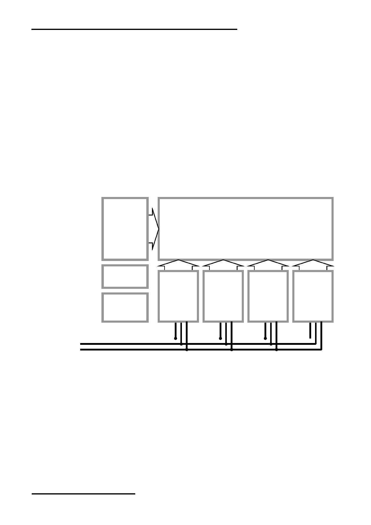
1.3 Block Diagram
COM1
LCD Panel
|
256 x 64 pixels
COM64
LED
BLA
Backlight
Circuit
VDD
Power and
SBN0064G
SBN0064G
SBN0064G
SBN0064G
VSS
LCD Booster
or
or
or
or
VOUT
Circuit
equivalent
equivalent
equivalent
equivalent
V0
DB0 - DB7
RS, R/W, E, /RST
CSA, CSB, CSC
URL: www.topwaydisplay.com
Document Name: LM6800ACW-1-Manual-Rev0.2
Page: 3 of 10
TOPWAY
LCD Module User Manual
LM6800ACW-1
1.4 Terminal Functions
Pin
Pin
No. Name
I/O
Descriptions
1
VSS Power Negative Power Supply, Ground (0V)
2
VDD Power Positive Power Supply
3
V0
Input LCD Contrast reference
4
VOUT Output Power Booster output for V0
5
RS
Input RS = H; DB0 – DB7 = Display RAM data
RS = L; DB0 – DB7 = Instruction data
6
R/W
Input In read mode
7
E
Input
R/W = H;
Data read form the LCD module,
data appears at DB0 – DB7 and can be read by the host
while, E = H and the device is being selected
In write mode
R/W = L;
Data write to the LCD module,
data appears at DB0 – DB7 will be written into the LCD module
at E = H L and device is being selected
8
DB0
I/O
Data bus:
:
:
:
Three state I/O terminal for display data or instruction data
15
DB7
I/O
16
CSA
Input Chip selection, enable access to each section of the LCD module
17
CSB
Input
CSC CSB CSA Function
18
CSC
Input
0
0
0
Enable access of the Left-Most Section (64 column)
of the LCD module
0
0
1
Enable access of the Middle-Left Section (64 column)
of the LCD module
0
1
0
Enable access to the Middle-Right Section (64 column)
of the LCD module
0
1
1
Enable access to the Right-Most Section (64 column)
of the LCD module
1
x
x
Disable all the access to the LCD module
19
/RST
Input Reset signal
/RST = L,
Display off
display start line register becomes 0
no command or instruction data could be accepted
/RST = H,
Normal running
20
BLA Power Positive Power Supply for LED backlight
URL: www.topwaydisplay.com
Document Name: LM6800ACW-1-Manual-Rev0.2
Page: 4 of 10
TOPWAY
LCD Module User Manual
LM6800ACW-1
2. Absolute Maximum Ratings
Items
Symbol
Min.
Max.
Unit
Condition
Supply Voltage
V DD
0
7.0
V
V SS = 0V
Operating Temperature
T OP
-20
70
C
No Condensation
Storage Temperature
T ST
-30
80
C
No Condensation
Cautions:
Any Stresses exceeding the Absolute Maximum Ratings may cause substantial damage to the
device. Functional operation of this device at other conditions beyond those listed in the
specification is not implied and prolonged exposure to extreme conditions may affect device
reliability.
3. Electrical Characteristics
3.1 DC Characteristics
V SS =0V, V DD =5V, T OP =25 C
Items
Symbol
MIN.
TYP.
MAX.
Unit
Applicable Pin
Operating Voltage
V DD
4.8
5.0
5.2
V
VDD
Input High Voltage
V IH
3.5
-
V DD
V
RS, R/W, E, DB0-DB7
Input Low Voltage
V IL
0
-
0.4
V
CSA, CSB, CSC
Operating Current
I DD
-
6.0
18
mA
VDD, VSS
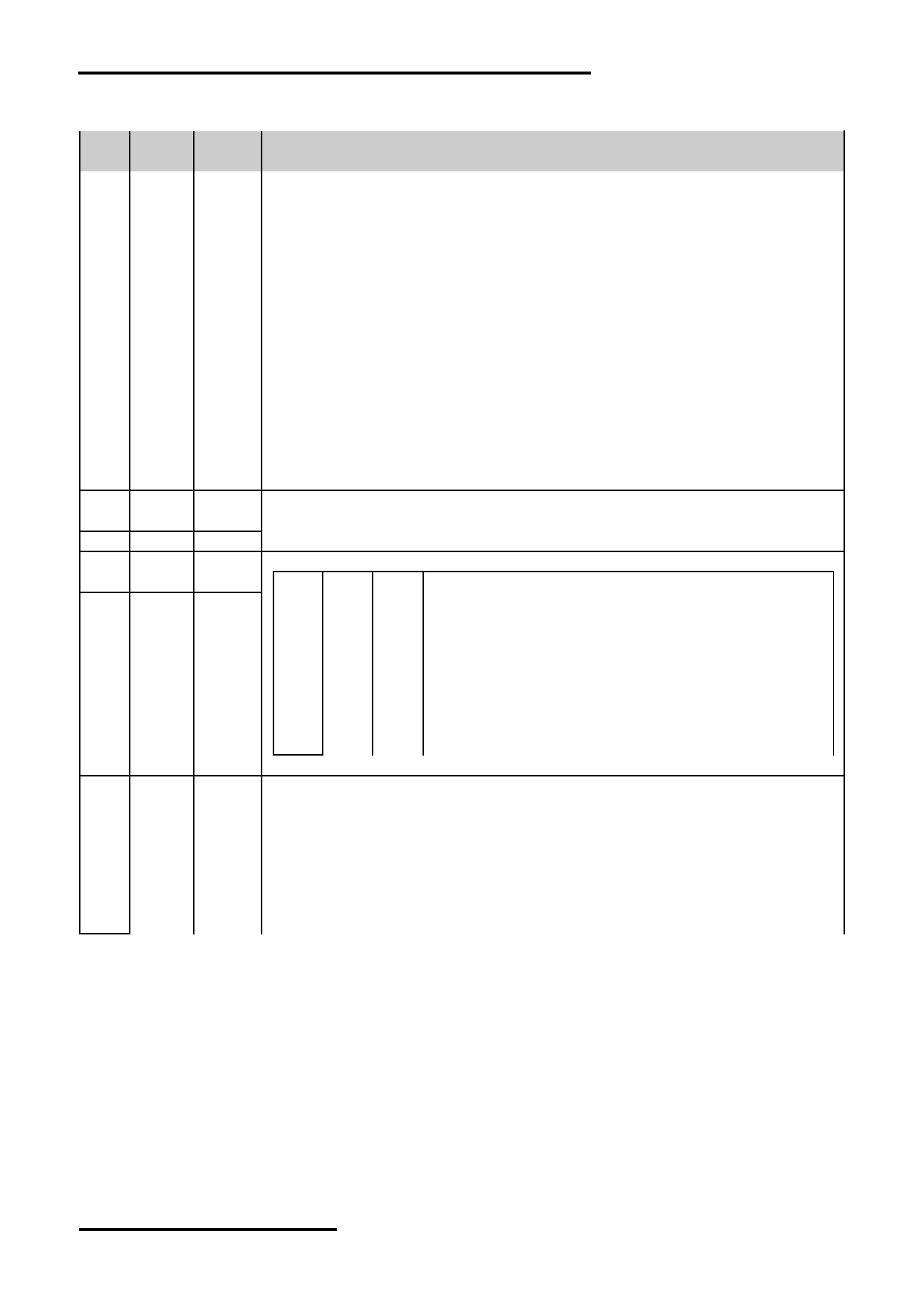
3.2 LED Backlight Circuit Characteristics
VSS=0V, If BLA =120mA, T OP =25 C
Items
Symbol
MIN.
TYP.
MAX.
Unit
Applicable Pin
Forward Voltage
Vf BLA
-
5.0
-
V
BLA
Forward Current
If BLA
-
-
120
mA
BLA
BLA
VSS
URL: www.topwaydisplay.com
Document Name: LM6800ACW-1-Manual-Rev0.2
Page: 5 of 10
TOPWAY
LCD Module User Manual
LM6800ACW-1
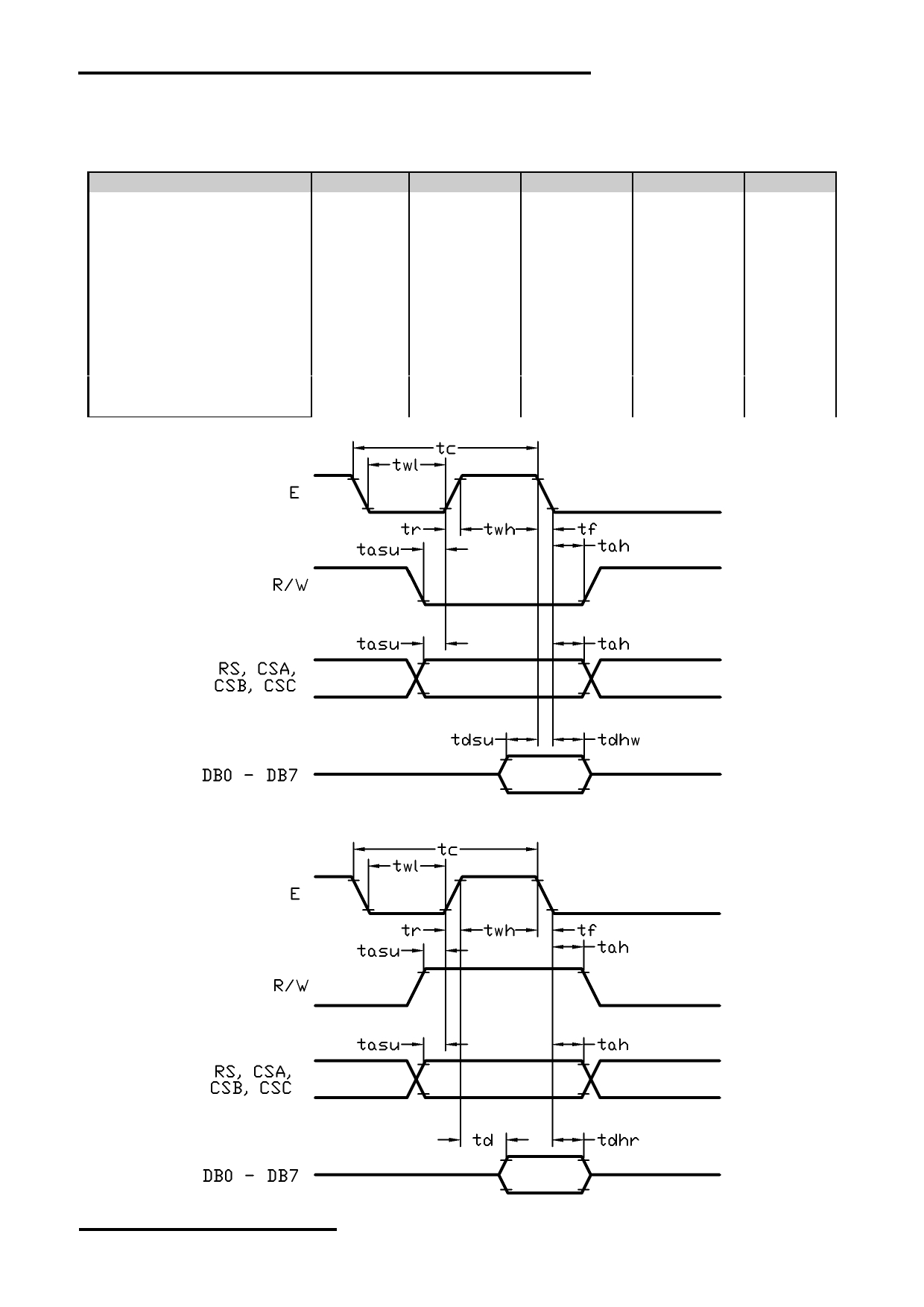
3.3 AC Characteristics
V SS =0V, V DD =5V, T OP =25 C
Item
Symbol
MIN.
TYP.
MAX.
Unit
E cycle time
tc
26
-
-
us
E high level width
twh
700
-
-
ns
E low level width
twl
700
-
-
ns
E rise time
tr
-
-
18
ns
E fall time
tf
-
-
18
ns
Address set-up time
tasu
240
-
-
ns
Address hold time
tah
50
-
-
ns
Data set-up time
tdsu
300
-
-
ns
Data delay time
td
-
-
480
ns
Data hold time (write)
tdhw
15
-
-
ns
Data hold time (read)
tdhr
30
-
-
ns
Host Write Timing Diagram
Host Read Timing Diagram
URL: www.topwaydisplay.com
Document Name: LM6800ACW-1-Manual-Rev0.2
Page: 6 of 10
TOPWAY
LCD Module User Manual
LM6800ACW-1
4. Function Specifications
4.1 Basic Setting
To drive the LCD module correctly and provide normally display, please use the following setting
Display start line (Z address)= 0
LCD Display = on
Note:
These setting/commands should issue to all controllers while start up.
See the Display Control Instructions section for details.
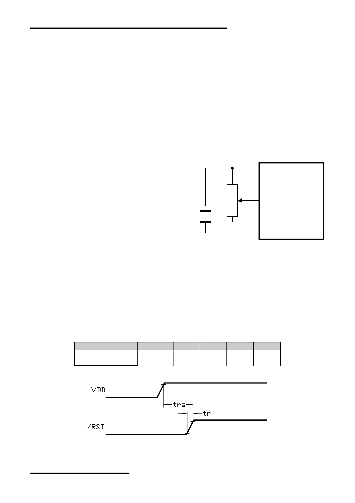
4.2 Adjusting the LCD display contrast
A Variable-Resistor must be connected to
LCD module
the LCD module for providing a reference to
V0. Adjusting the VR will result the change
VDD
of LCD display contrast.
The recommended value of VR is 25k to 50k
VR
V0
VOUT
VSS
4.3 Resetting the LCD module
The LCD module should be initialized by setting /RST terminal at low level when turning the power
on.
When /RST pull low, the LCD module will:
- Display off
- Display start line register becomes 0. (Z-address=0)
While /RST is low, no instruction can be accepted except status read. Therefore, execute other
instructions after making sure that DB4=0 (clear /RST) and DB7=0 (ready) by status read
instruction. The conditions of power supply at initial power up are as follow:
Item
Symbol
MIN.
TYP.
MAX.
Unit
Reset time
trs
2.0
-
-
us
Rise time
tr
-
-
150
ns
URL: www.topwaydisplay.com
Document Name: LM6800ACW-1-Manual-Rev0.2
Page: 7 of 10
TOPWAY
LCD Module User Manual
LM6800ACW-1
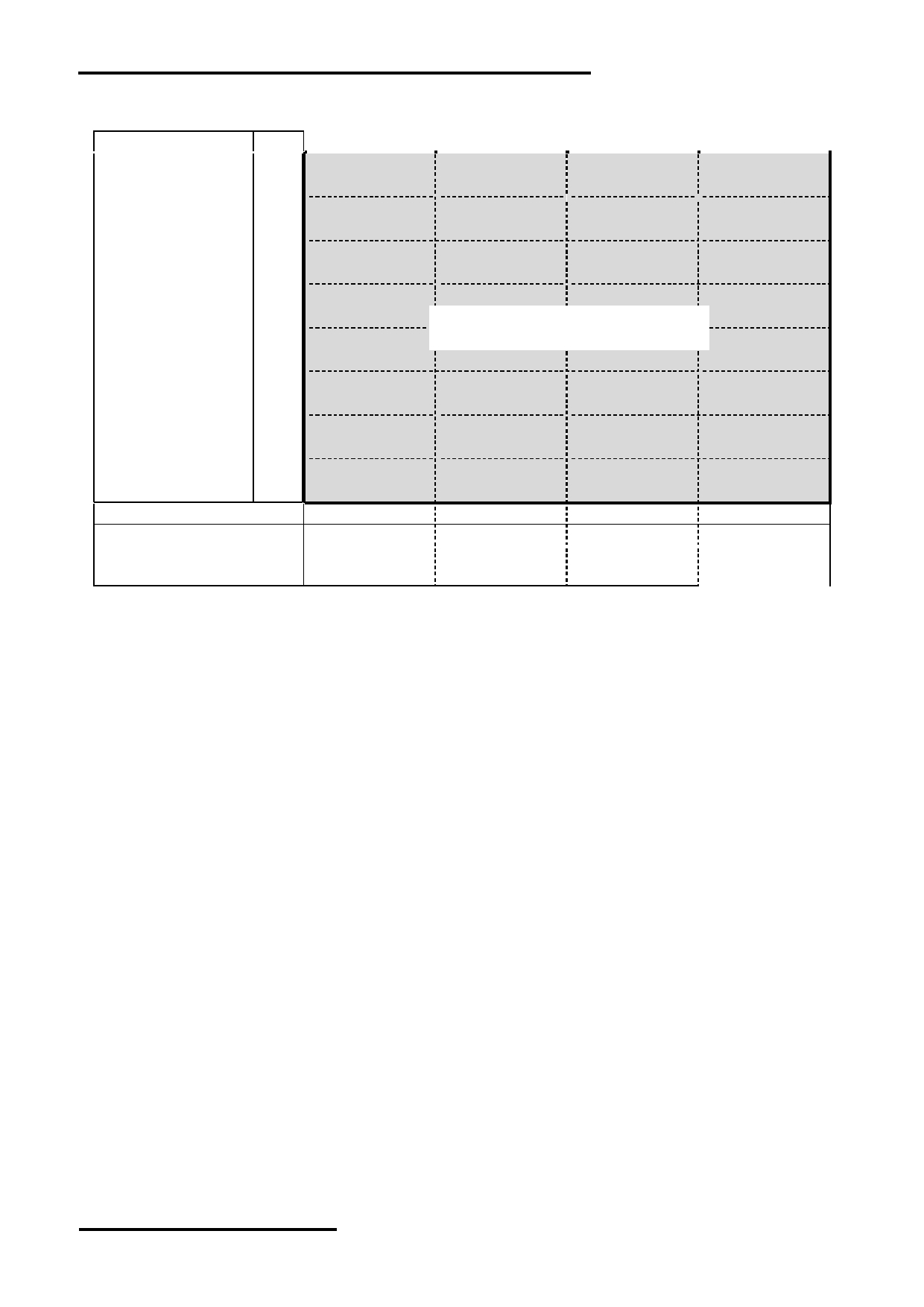
4.4 Display Memory Map
Page (X) address data
LCD Display (front view)
D0
0
:
D7
D0
1
:
D7
D0
2
:
D7
D0
3
:
D7
D0
4
:
256x64 pixels
D7
D0
5
:
D7
D0
6
:
D7
D0
7
:
D7
Column(Y) Address
00h 3Fh
00h 3Fh
00h 3Fh
00h 3Fh
Chip Select CSA
0
1
0
1
Chip Select CSB
0
0
1
1
Chip Select CSC
0
0
0
0
Note:
1) Display start line (Z address) = 0
2) The Display Data store separately in four drivers.
4.5 Internal Registers
There are three registers in each section of LCD module. Each of them could be controlled
independently.
Page (X) Address Register
X address register designates pages of the internal display data RAM. Count function is not
available. The address should set by instruction.
Column (Y) Address Counter
Y address counter designates address of the internal display data RAM. It could be set by
instruction and increased by 1 automatically by read or write display data operations.
Display Start Line (Z) Register
Z address register indicates of display data RAM to LCD top line. It may be used for scrolling the
display pattern on the LCD.
URL: www.topwaydisplay.com
Document Name: LM6800ACW-1-Manual-Rev0.2
Page: 8 of 10
TOPWAY
LCD Module User Manual
LM6800ACW-1
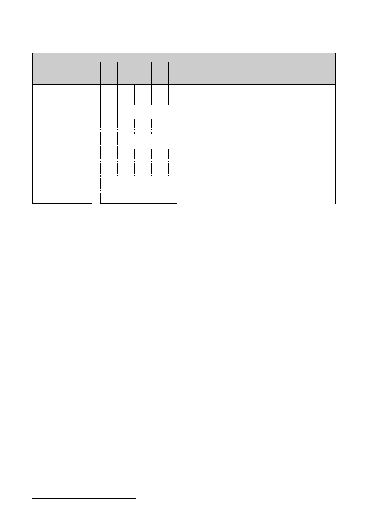
4.6 Display Control Instructions
Code
Instructions
Function
Controls the display on or off. Internal status and display
Display on/off
0 0 0 0 1 1 1 1 1 1/0 data in RAM is not affected
0=off, 1=on
Set Column (Y)
0 0 0 1
Y address (0-63)
Set the Column address into the Y address counter
Address
Set Page (X)
X address
0 0 1 0 1 1 1
Set the Page address into the X address register
Address
(0-7)
Set Display Start
Z address
0 0 1 1
Indicates the display data RAM displayed at the top of the
Line (Z address)
(0-63)
screen
Read status
Busy=L, Driver ready; Busy=H, Driver busy
Status Read
0 1
0
0 0 0 0
on/off=L, Display is on; on/off=H, Display is off
Reset=L, Normal Running; Reset=H, reset
Write display data into display data RAM,
Write Display Data 1 0
Write data
After writing instruction, Y address counter increased by 1
automatically
Read Display Data 1 1
Read data
Read display data form the display data RAM
Note:
*1. For the details of the Display Control Instructions, please refer to Samsung SBN0064G
handbook.
URL: www.topwaydisplay.com
Document Name: LM6800ACW-1-Manual-Rev0.2
Page: 9 of 10

TOPWAY
LCD Module User Manual
LM6800ACW-1
5. Design and Handling Precaution
Please refer to "LCD-Module-Design-Handling-Precaution.pdf".
URL: www.topwaydisplay.com
Document Name: LM6800ACW-1-Manual-Rev0.2
Page: 10 of 10