LMB162XFW
LCD Module User Manual
Prepared by:
Checked by:
Approved by:
Wang
Date:2015-10-08
Date:
Date:
Rev. Descriptions
Release Date
0.1
Prelimiay release
2008-09-24
0.2
Update Absolute Maximum Ratings
2015-07-28
0.3
Update Display Specifications
2015-10-08
URL: www.topwaydisplay.com
Document Name: LMB162XFW-Manual-Rev0.3
Page: 1 of 10

TOPWAY
LCD Module User Manual
LMB162XFW
Table of Content
1. Basic Specifications .............................................................................................................. 3
1.1
Display Specifications ....................................................................................................... 3
1.2
Mechanical Specifications ................................................................................................. 3
1.3
Block Diagram .................................................................................................................. 3
1.4
Terminal Functions ........................................................................................................... 4
2. Absolute Maximum Ratings .................................................................................................. 5
3. Electrical Characteristics ...................................................................................................... 5
3.1
DC Characteristics ............................................................................................................ 5
3.2
LED Backlight Circuit Characteristics ................................................................................ 5
3.3
AC Characteristics ............................................................................................................ 6
4. Function Specifications ......................................................................................................... 7
4.1
Basic Setting ..................................................................................................................... 7
4.2
Resetting the LCD module ................................................................................................ 7
4.3
Adjusting the LCD display contrast ................................................................................... 7
4.4
Display Memory Map ........................................................................................................ 8
4.5
Display Commands ......................................................................................................... 10
5. Design and Handling Precaution ........................................................................................ 10
URL: www.topwaydisplay.com
Document Name: LMB162XFW-Manual-Rev0.3
Page: 2 of 10
TOPWAY
LCD Module User Manual
LMB162XFW
1. Basic Specifications
1.1 Display Specifications
1) LCD Display Mode
: STN-Blue, Negative, Transmissive
2) Display Color
: Display Data = “1” : Light Gray (*1)
: Display Data = “0” : Dark Blue (*2)
3) Viewing Angle
: 6H
4) Driving Method
: 1/16 duty, 1/5 bias
5) Back Light
: White LED backlight
Note:
*1. Color tone may slightly change by Temperature and Driving Condition.
*2. The Color is defined as the inactive / background color
1.2 Mechanical Specifications
1) Outline Dimension
: 53.0 x 20.0 x 9.1MAX
(See attached Outline Drawing for details)
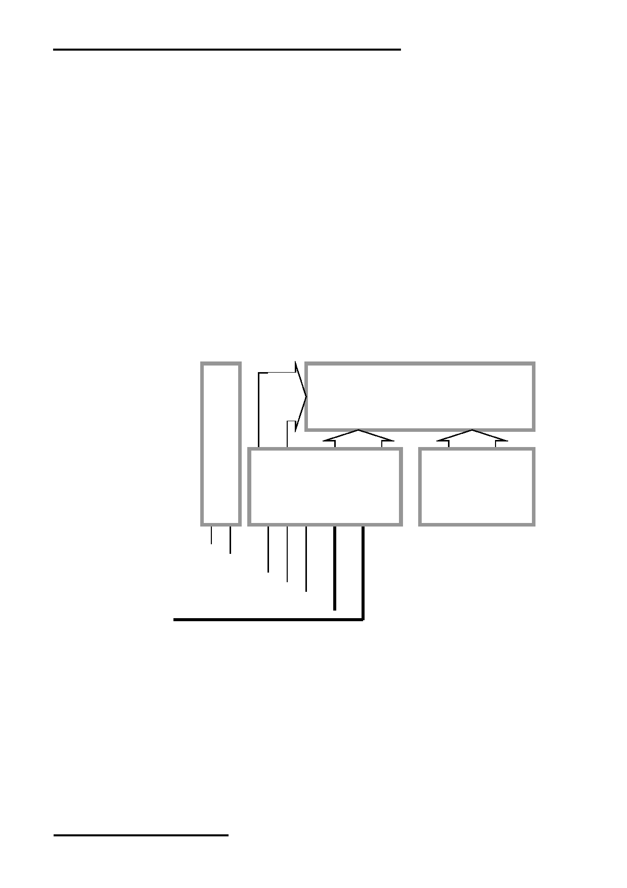
1.3 Block Diagram
LCD Panel
16 x 2 Char (5x8dots)
ST7066U
ST7065
or
or
equivalent
equivalent
BLA
BLK
VDD
VSS
V0
DB0 – DB7
RS, R/W, E
URL: www.topwaydisplay.com
Document Name: LMB162XFW-Manual-Rev0.3
Page: 3 of 10
TOPWAY
LCD Module User Manual
LMB162XFW
1.4 Terminal Functions
Pin No.
Pin
Name
I/O
Descriptions
1
VSS
Power Power supply, Ground (0V)
2
VDD
Power Positive power supply
3
V0
Power LCD contrast reference supply
4
RS
Input Register Select
RS=HIGH: transferring display data
RS=LOW: transferring instruction data
5
R/W
Input Read / Write Control bus:
R/W=HIGH: Read mode selected
R/W=LOW: Write mode selected
6
E
Input Data Enable
7
DB0
I/O
Bi-directional tri-state Data bus
:
:
In 8 bit mode, DB0 ~ DB7 are in use
14
DB7
In 4 bit mode, DB4 ~ DB7 are in use, DB0~DB3 leave open
15
BLA
Power Backlight positive supply
16
BLK
Power Backlight negative supply
URL: www.topwaydisplay.com
Document Name: LMB162XFW-Manual-Rev0.3
Page: 4 of 10
TOPWAY
LCD Module User Manual
LMB162XFW
2. Absolute Maximum Ratings
Items
Symbol
Min.
Max.
Unit Condition
Supply Voltage
V DD
0
6.0
V
V SS = 0V
Input Voltage
V IN
0
V DD
V
V SS = 0V
Operating Temperature
T OP
-20
70
C
No Condensation
Storage Temperature
T ST
-30
80
C
No Condensation
Cautions:
Any Stresses exceeding the Absolute Maximum Ratings may cause substantial damage to the device. Functional
operation of this device at other conditions beyond those listed in the specification is not implied and prolonged exposure
to extreme conditions may affect device reliability.
3. Electrical Characteristics
3.1 DC Characteristics
V SS =0V, V DD =5.0V, T OP =25 C
Items
Symbol
MIN.
TYP
MAX.
Unit Condition /
.
Application Pin
Operating Voltage
V DD
4.7
5.0
5.3
V
VDD
Input High Voltage
V IH
0.8xV DD
-
V DD
V
RS, R/W, E, DB0 ~ DB7
Input Low Voltage
V IL
V SS
-
0.5
V
Output High Voltage
V OH
0.7xV DD
-
V DD
V
I OH =-0.1mA, DB0 ~ DB7
Output Low Voltage
V OL
V SS
-
0.5
V
I OL =0.1mA, DB0 ~ DB7
Operating Current
I DD
-
1.3
3.0
mA VDD, VSS
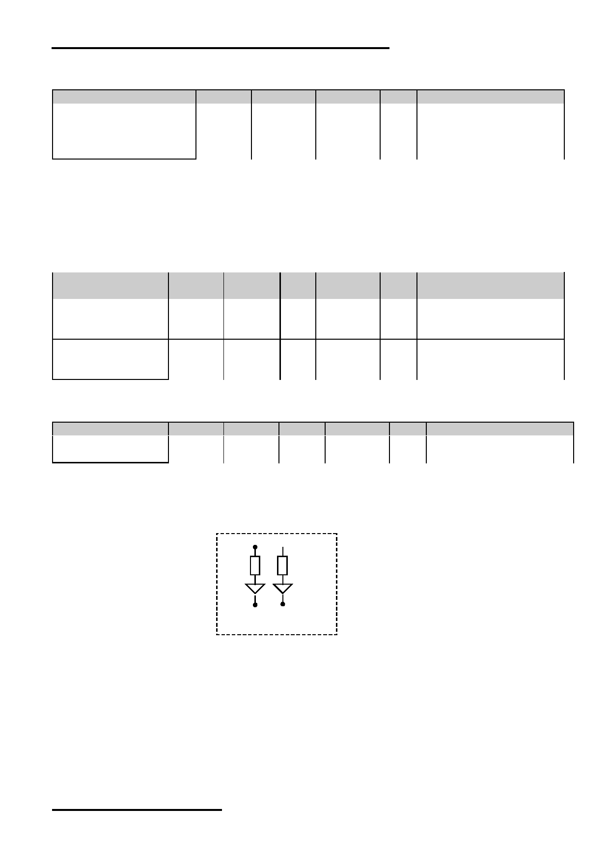
3.2 LED Backlight Circuit Characteristics
V BLK =0V, If BLA =16mA, T OP =25 C
Items
Symbol
MIN.
TYP.
MAX.
Unit Applicable Pin
Forward Voltage
Vf BLA
-
5.0
-
V
BLA
Forward Current
If BLA
-
16
40
mA BLA
Cautions:
Exceeding the recommended driving current could cause substantial damage to the backlight and shorten its lifetime.
BLA
BLK
No. of LED = 2 pcs
URL: www.topwaydisplay.com
Document Name: LMB162XFW-Manual-Rev0.3
Page: 5 of 10
TOPWAY
LCD Module User Manual
LMB162XFW
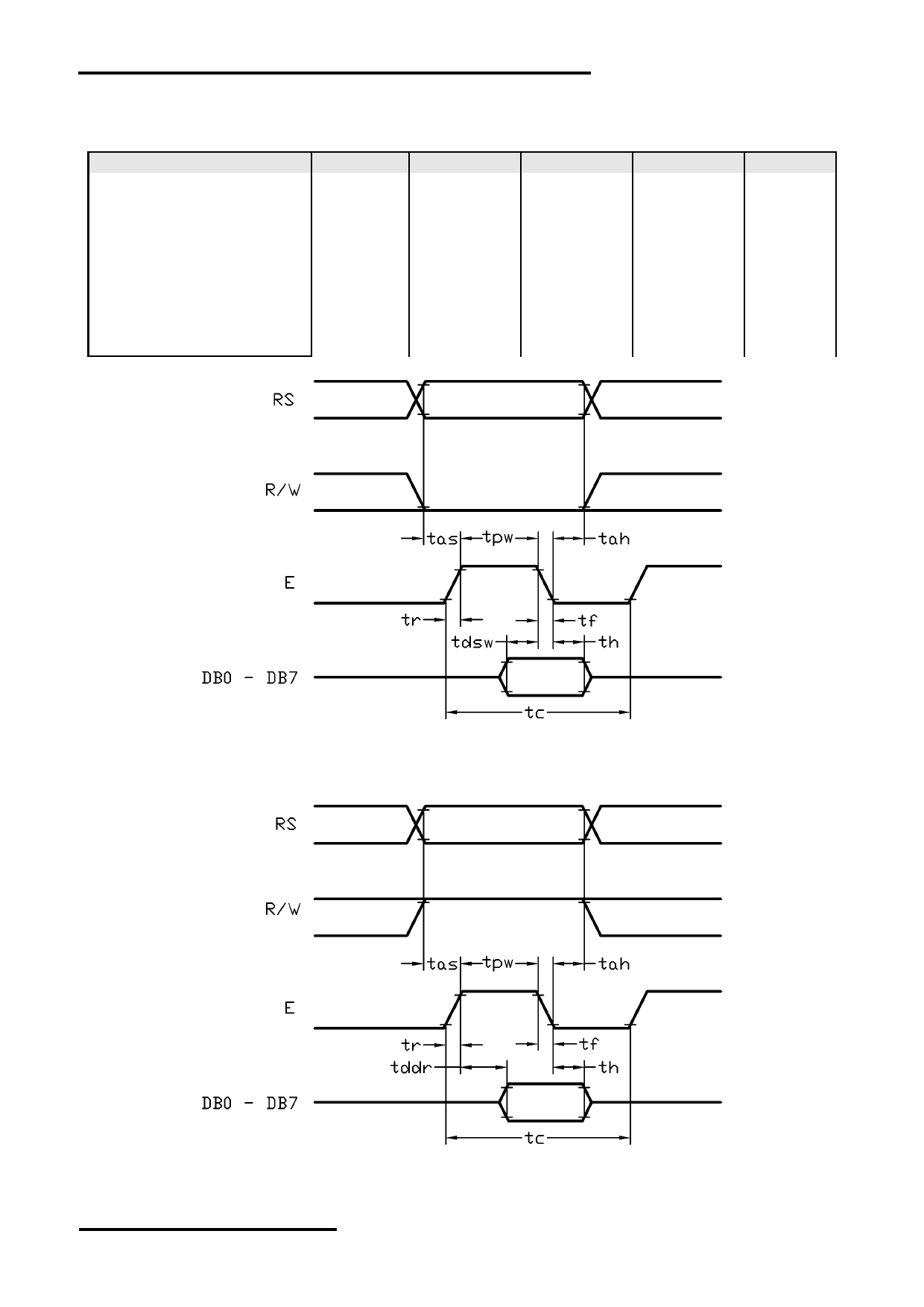
3.3 AC Characteristics
V SS =0V, V DD =5V, T OP =25 C
Item
Symbol
MIN.
TYP.
MAX.
Unit
E cycle time
tc
1500
-
-
ns
E high level width
tpw
175
-
-
ns
E rise time
tr
-
-
20
ns
E fall time
tf
-
-
20
ns
Address set-up time
tas
5
-
-
ns
Address hold time
tah
13
-
-
ns
Data set-up time
tdsw
50
-
-
ns
Data delay time
tddr
-
-
125
ns
Data hold time
th
13
-
-
ns
Host Write Timing Diagram
Host Read Timing Diagram
URL: www.topwaydisplay.com
Document Name: LMB162XFW-Manual-Rev0.3
Page: 6 of 10
TOPWAY
LCD Module User Manual
LMB162XFW
4. Function Specifications
4.1 Basic Setting
To drive the LCD module correctly and provide normally display, please use the following setting
- N=1, 2-line display
- F=0, 5x8 dots font
- D=1, display on
Note:
*1. These setting/commands should issue to the LCD module while start up.
*2. See the Display Commands section for details.
4.2 Resetting the LCD module
When turning on the VDD and VSS power supply, LCD module will execute the reset routine
automatically. It takes about 50ms. After the reset routine, the LCD module status will be as follow:
- Display clear
- DL=1,
8-bit interface
- N=0,
1-line display
- F=0,
5x8 dot character font
- D=0,
Display off
- C=0,
Cursor off
- B=0,
Blinking off
- I/D=1,
Increment by 1
- S=0,
No shift
Note:
*1. Reset routine could not generate the Basic Setting
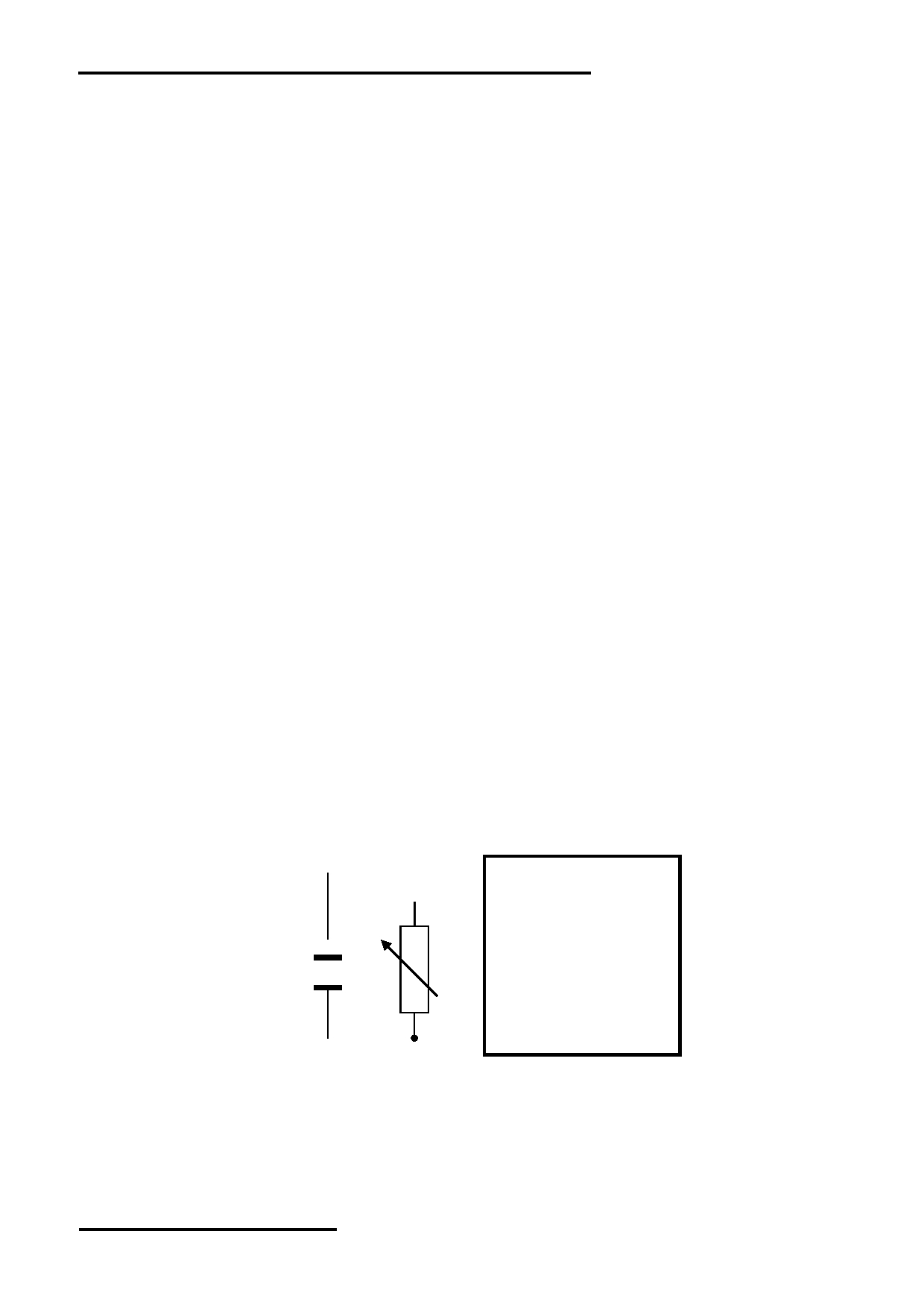
4.3 Adjusting the LCD display contrast
A Variable-Resistor must be connected to the LCD module for providing a reference supply to V0.
Adjusting the VR will result the change of LCD display contrast. The recommended value of VR is
5k Ohm.
LCD Module
VDD
V0
VR
VSS
URL: www.topwaydisplay.com
Document Name: LMB162XFW-Manual-Rev0.3
Page: 7 of 10
TOPWAY
LCD Module User Manual
LMB162XFW
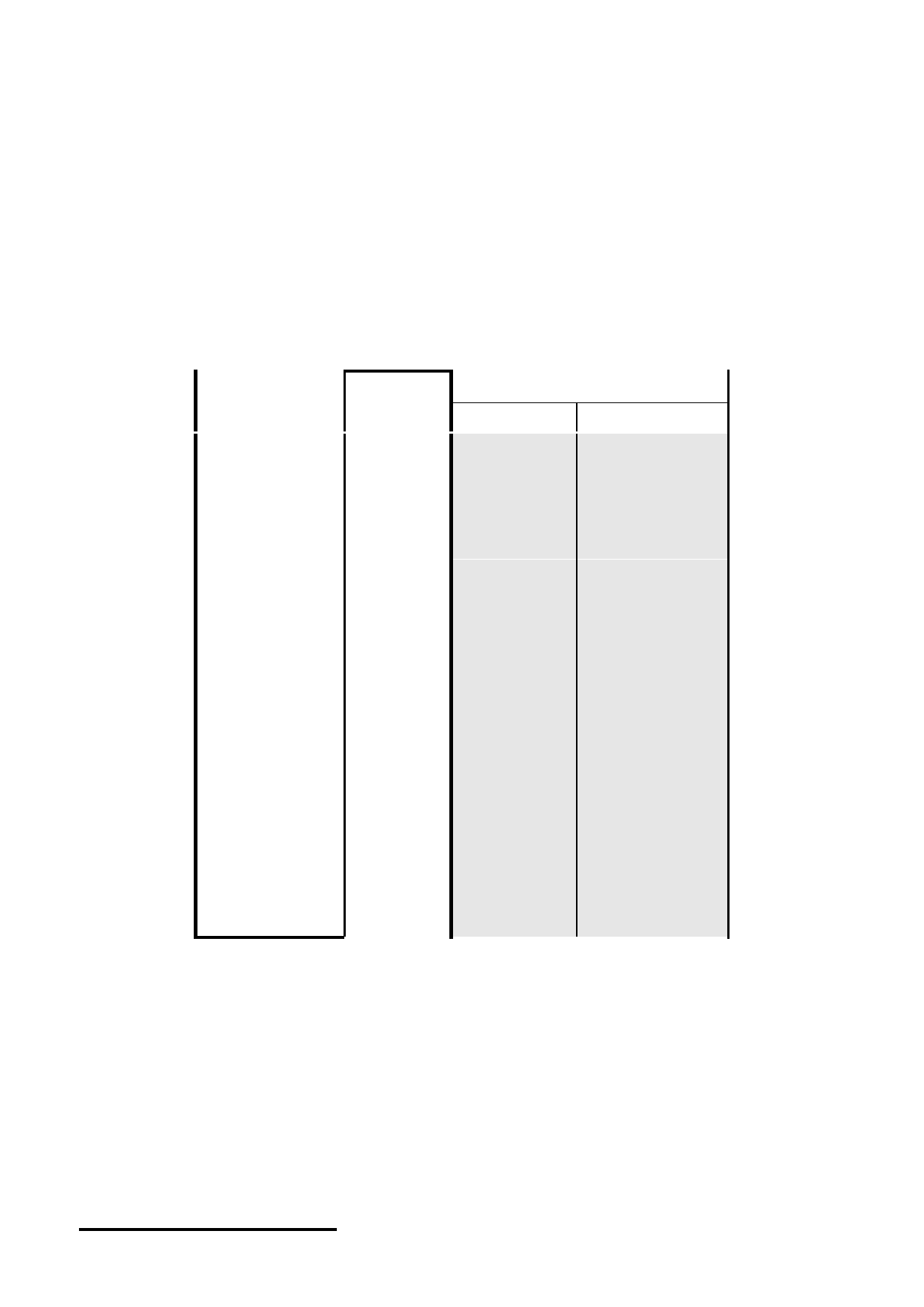
4.4 Display Memory Map
There are two main memory-areas in the LCD module for display.
- Character Generator RAM (CGRAM)
- Display Data RAM (DDRAM)
4.4.1 Character Generator RAM (CGRAM)
Character Generator RAM is for storing the User-defined Characters (5x8 dots font).
Totally 8 User-defined Characters (character code = 00h ~ 07h) could be created.
The User-defined Character Codes are 00h and 07h. They could be called into DDRAM as normal
character.
User-defined
CGRAM Data (Font Pattern)
Character
CGRAM
Code
Address
D7 ~ D5
D4 ~ D0
00h
00h
01h
:
Not Use
5 x 8 dots
(08h)
06h
font pattern
07h
08h
01h
09h
:
Not Use
5 x 8 dots
(09h)
0Eh
font pattern
0Fh
10h
02h
11h
:
Not Use
5 x 8 dots
(0Ah)
16h
font pattern
17h
18h
03h
19h
:
Not Use
5 x 8 dots
(0Bh)
1Eh
font pattern
1Fh
20h
04h
21h
:
Not Use
5 x 8 dots
(0Ch)
26h
font pattern
27h
28h
05h
29h
:
Not Use
5 x 8 dots
(0Dh)
2Eh
font pattern
2Fh
30h
06h
31h
:
Not Use
5 x 8 dots
(0Eh)
36h
font pattern
37h
38h
07h
39h
:
Not Use
5 x 8 dots
(0Fh)
3Eh
font pattern
3Fh
CGRAM Address Map
URL: www.topwaydisplay.com
Document Name: LMB162XFW-Manual-Rev0.3
Page: 8 of 10
TOPWAY
LCD Module User Manual
LMB162XFW
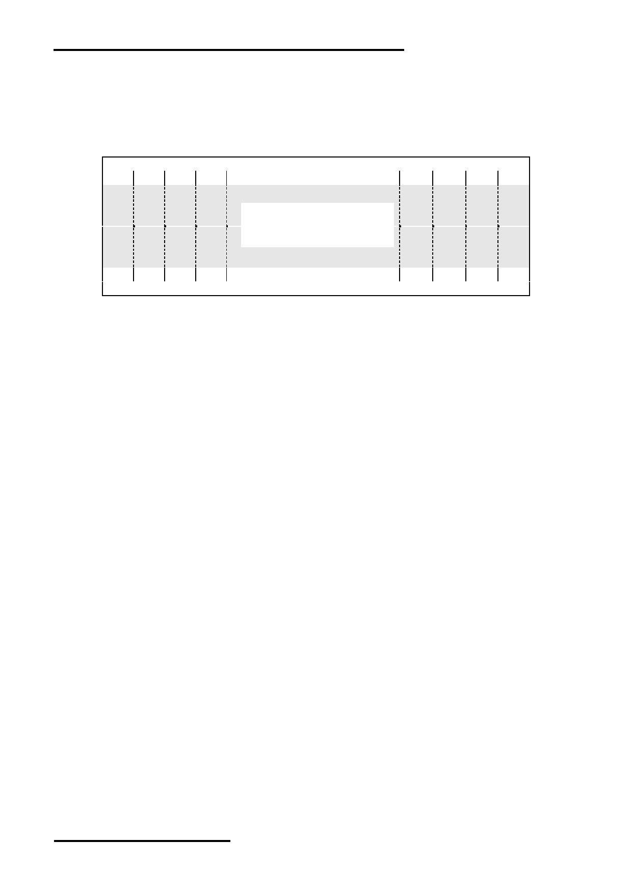
4.4.2 Display Data RAM (DDRAM)
ROM Characters (Character Code = 10h ~ FFh) could be written into DDRAM for displaying the
Character (5x8 dots font). User-defined Characters (Character Code = 00h ~ 07h) stored in
CGRAM could also be use. Calling Character Code 08h ~ 0Fh will call out User-defined
Characters 00h ~ 07h respectively.
DDRAM Address
00h 01h 02h 03h
0Ch 0Dh 0Eh 0Fh
16 x 2 Characters
(5x8 dots font)
40h 41h 42h 43h
4Ch 4Dh 4Eh 4Fh
DDRAM Address
DDRAM Address Map
Note:
*1. The mapping is based on top view of the LCD module
*2. N=1, 2-line display
*3. F=0, 5x8 dots font
*4. D=1, display on
4.4.3 Character Code Rom
Please refer to ST7066U-0A Data sheet
URL: www.topwaydisplay.com
Document Name: LMB162XFW-Manual-Rev0.3
Page: 9 of 10
TOPWAY
LCD Module User Manual
LMB162XFW
4.5 Display Commands
Code
No. Instructions
Function
Clear
Write “20h” to DDRAM and
1
0
0
0
0
0
0
0
0
0
1
Display
set DDRAM address (AC) to “00h”
Return
Set DDRAM address (AC) to “00h” and
2
0
0
0
0
0
0
0
0
1
x
Home
return cursor to its original position if shifted
(DDRAM contents are not change)
Set cursor moving direction and specify display
shift, during data read and write of DDRAM and
Entry Mode
CGRAM.
3
0
0
0
0
0
0
0
1 I/D S
Set
S=1, screen shifting;
S=0, no screen shifting
I/D=1, AC=AC+1 and if S=1, screen shift left
I/D=0, AC=AC-1 and if S=0, screen shift right
Display
D=1, display on;
D=0, display off
4
0
0
0
0
0
0
1
D C B C=1, cursor on;
ON/OFF
C=0, cursor off
B=1, cursor blinking on; B=0, cursor blinking off
Move the cursor or shift the display, where
Cursor or
DDRAM contents.
5
0
0
0
0
0
1 S/C R/L x
x
Display Shift
S/C=1, shift screen;
S/C=0, shift cursor
R/L=1, to right-side;
R/L=0, to left side
(if S/C=1, AC will not be changed)
Function
DL=1, 8-bit interface;
DL=0, 4-bit interface
6
0
0
0
0
1 DL N F
x
x
Set
N=1, 2-line display;
N=0, 1-line display
F=1, 5x11 dots font;
F=0, 5x8 dots font
Set CGRAM
7
0
0
0
1 AC5 AC4 AC3 AC2 AC1 AC0 Set CGRAM address in address counter
address
Set DDRAM
8
0
0
address
1 AC6 AC5 AC4 AC3 AC2 AC1 AC0 Set DDRAM address in address counter
Read Busy flag
Check the system status and get the address
9
0
1 BF AC6 AC5 AC4 AC3 AC2 AC1 AC0 counter content (AC6~AC0).
& address
BF=1, busy;
BF=0, ready
Write data
Write the data into internal RAM, where the
10
1
0 D7 D6 D5 D4 D3 D2 D1 D0
to RAM
address counter pointing at.
Read data
Read the data from internal RAM, where the
11
1
1 D7 D6 D5 D4 D3 D2 D1 D0
from RAM
address counter pointing at.
Note:
*1. Do not use any other command not listed, or the system malfunction may result.
*2. For the details of the Display Commands, please refer to ST7066U datasheet.
5. Design and Handling Precaution
Please refer to "LCD-Module-Design-Handling-Precaution.pdf".
URL: www.topwaydisplay.com
Document Name: LMB162XFW-Manual-Rev0.3
Page: 10 of 10