LMK050DICFWD-AKA
LCD Module User Manual
Prepared by:
Checked by:
Approved by:
HeHongLiang
Date: 2017-10-25
Date:
Date:
Rev. Descriptions
Release Date
0.1
Preliminary
2017-04-25
0.2
Assemble Precaution
2017-10-25
NURL: www.topwaydisplay.com
Document Name: LMK050DICFWD-AKA-Manual-Rev0.2
Page: 1 of 9

TOPWAY
LCD Module User Manual
LMK050DICFWD-AKA
Table of Content
1. General Specification ............................................................................................................ 3
2. Block Diagram ........................................................................................................................ 3
3. Terminal Function .................................................................................................................. 4
3.1
K1 Terminal(DVI Right angle connector) ................................................................................................................ 4
4. Absolute Maximum Ratings .................................................................................................. 4
5. Electrical Characteristics ...................................................................................................... 5
5.1
DC Characteristics ................................................................................................................................................. 5
5.2
DC Characteristics(LVDS) ..................................................................................................................................... 5
5.3
POWER ON/OFF SEQUENCE .............................................................................................................................. 5
6. AC Characteristics ................................................................................................................. 6
6.1
AC Characteristics(LVDS) ...................................................................................................................................... 6
6.2
AC Characteristics(TFT) ........................................................................................................................................ 7
7. Optical Characteristics .......................................................................................................... 8
8. Precautions for Use of LCD Modules ................................................................................... 8
8.1
Handling Precautions ................................................................................................................. 错误 ! 未定义书签。
8.2
Storage precautions ................................................................................................................... 错误 ! 未定义书签。
8.3
Transportation Precautions ........................................................................................................ 错误 ! 未定义书签。
9 . Assemble Precaution ............................................................................................................... 9
NURL: www.topwaydisplay.com
Document Name: LMK050DICFWD-AKA-Manual-Rev0.2
Page: 2 of 9

TOPWAY
LCD Module User Manual
LMK050DICFWD-AKA
1. General Specification
Signal Interface :
LVDS (JEIDA 24 bits)
Display Mode :
Transmissive with Normally White
Screen Size :
5.0 inch
Outline Dimension :
160.0 x 105.0 x 22.0(mm)
(see outline drawing for details)
Active Area :
108.0x 64.8(mm)
Number of dots :
800x 3 (RGB) x 480
Dot Pitch :
0.045 ( W ) x 0.135 ( H ) (mm)
Pixel Configuration :
R.G.B. Vertical Stripe
Backlight :
White LED
Viewing Direction :
6 o’clock ( Gray scale Inversion ) (*1)
12 o’clock (*2)
Operating Temperature :
-20 ~ +70°C
Storage Temperature :
-30 ~ +80°C
Note:
*1. For saturated color display content (eg. pure-red, pure-green, pure-blue or pure-colors -combinations).
*2. For “ color scales ” display content.
*3. Color tone may slightly change by temperature and driving condition.
2. Block Diagram
BL_PWM
Backlight Circuit
Touch Panel
USB_DM, SUB_DP
800(x3) x 480 pixels
Source Driver
VDD,GND
RX0+,RX0-,RX1+,RX1-
LVDS interface
Power Circuit
RX2+,RX2-,RX3+,RX3-
RxCLK+,RxCLK-
NURL: www.topwaydisplay.com
Document Name: LMK050DICFWD-AKA-Manual-Rev0.2
Page: 3 of 9
TOPWAY
LCD Module User Manual
LMK050DICFWD-AKA
3. Terminal Function
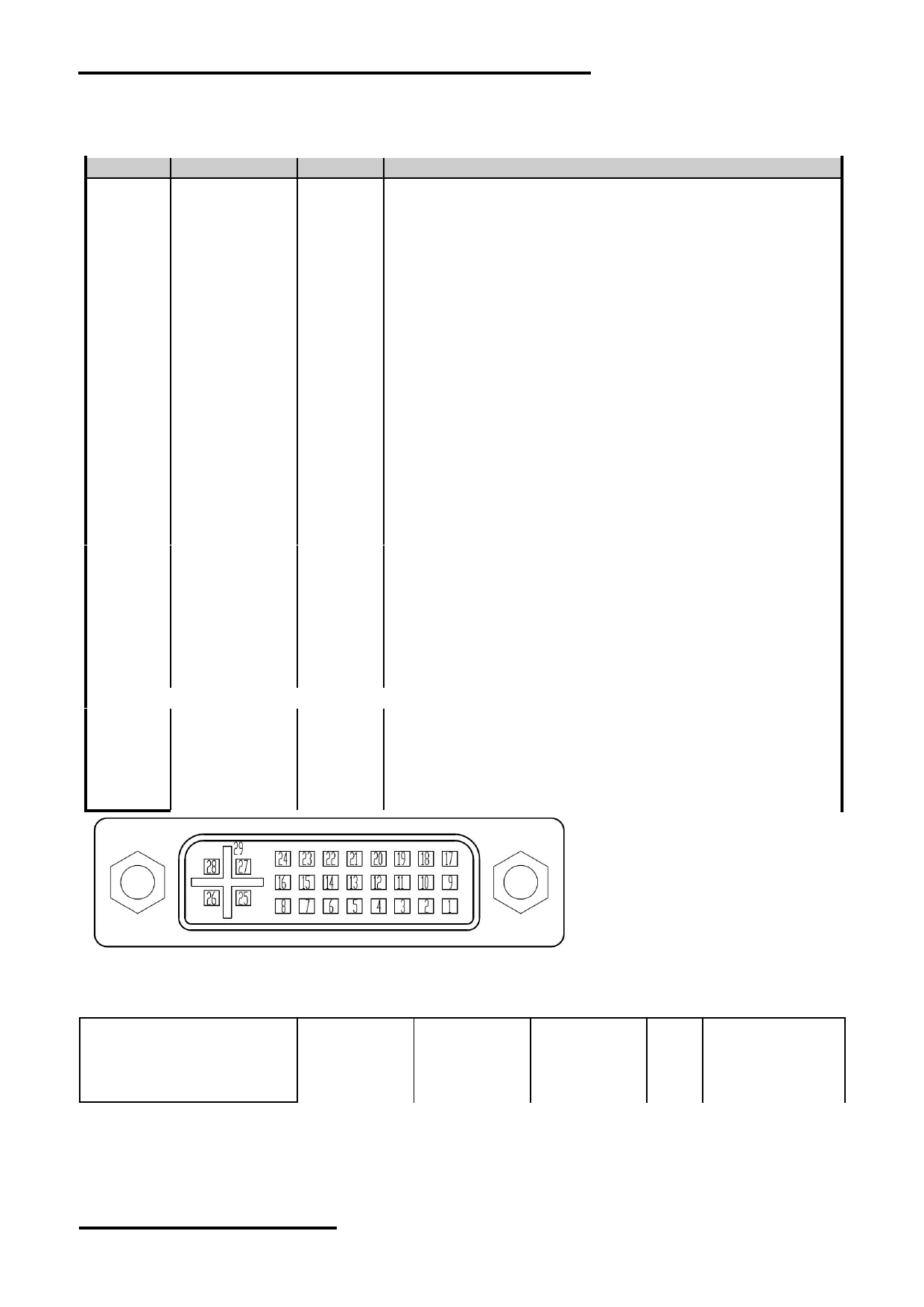
3.1 K1 Terminal(DVI Right angle connector)
Pin No.
Pin Name
IO
Descriptions
1
RX2-
Input
LVDS receiver negative signal channel 2
2
RX2+
Input
LVDS receiver positive signal channel 2
3
GND
Power Ground
4
BL_PWM
Input
Backlight dimming control(High actives)
PWM may be used to adjust the output brightness
5
NC
-
No connection
6
VDD
Power Positive Power Supply(5.0V)
7
VDD
Power Positive Power Supply(5.0V)
8
VDD
Power Positive Power Supply(5.0V)
9
RX1-
Input
LVDS receiver negative signal channel 1
10
RX1+
Input
LVDS receiver positive signal channel 1
11
GND
Power Ground
12
RX3-
Input
LVDS receiver negative signal channel 3
13
RX3+
Input
LVDS receiver positive signal channel 3
14
VDD
Power Positive Power Supply(5.0V)
15
GND
Power Ground
16
GND
Power Ground
17
RX0-
Input
LVDS receiver negative signal channel 0
18
RX0+
Input
LVDS receiver positive signal channel 0
19
GND
Power Ground
20
USB_DM
I/O
USB D- signal
21
USB_DP
I/O
USB D+ signal
22
GND
Power Ground
23
RXCLK+
Input
LVDS receiver positive signal clock
24
RXCLK-
Input
LVDS receiver negative signal clock
25
VDD
Power Positive Power Supply(5.0V)
26
VDD
Power Positive Power Supply(5.0V)
27
NC
-
No connection
28
NC
-
No connection
29
GND
Power Ground
4. Absolute Maximum Ratings
Items
Symbol
Min.
Max.
Unit Condition
Power Supply voltage
VDD
-0.3
5.5
V
Operating Temperature
T OP
-20
70
C
No Condensation
Storage Temperature
T ST
-30
80
C
No Condensation
Note:
*1. This rating applies to all parts of the module. And should not be exceeded.
*2. The operating temperature only guarantees operation of the circuit. The contrast, response speed,
and the other specification related to electro-optical display quality is determined at the room temperature, T OP =25 ℃
*3. Any Stresses exceeding the Absolute Maximum Ratings may cause substantial damage to the device. Functional
operation of this device at other conditions beyond those listed in the specification is not implied and prolonged
exposure to extreme conditions may affect device reliability.
NURL: www.topwaydisplay.com
Document Name: LMK050DICFWD-AKA-Manual-Rev0.2
Page: 4 of 9

TOPWAY
LCD Module User Manual
LMK050DICFWD-AKA
5. Electrical Characteristics
5.1 DC Characteristics
VDD=5.0V,GND=0V,T a =25 C
Items
Symbol
MIN.
TYP.
MAX.
Unit
Note
Supply Voltage
VDD
4.7
5.0
5.3
V
VDD Power Consumption
I dd
--
400
TBD
mA
*1
Input High Voltage
V IH
3.0
3.3
-
V
BL_PWM
Input Low Voltage
V IL
GND
-
0.3
V
BL_PWM
Note1:
*1. BL_PWM=Hi;
*3. Terminal circuit.
*2. Recommended BL_ PWM PWM Freq. is 3kHz.
5.2 DC Characteristics(LVDS)
VDD=5.0V,GND=0V,T a =25 C
Items
Symbol
MIN.
TYP.
MAX.
Unit
Note
Differential Input High
Threshold
V TH
-
-
100
mV
Differential Input Low
Threshold
V TL
-100
-
-
mV
Input Current
I IN
± 10
uA
Differential Input common
Mode voltage
V CMLVDS
1.65
-
2.1
V
LVDS DC timing diagram
5.3 POWER ON/OFF SEQUENCE
Parameter
Symbol
MIN.
TYP.
MAX.
Unit Note
VDD 5.0V to signal starting
Tp1
0
-
50
ms
Signal staring to backlight on
Tp2
150
-
-
ms
Signal off to VDD 3.0V
Tp3
0
-
50
ms
Backlight off to signal off
Tp4
150
-
-
ms
Interface Power On/Off Sequence
NURL: www.topwaydisplay.com
Document Name: LMK050DICFWD-AKA-Manual-Rev0.2
Page: 5 of 9
TOPWAY
LCD Module User Manual
LMK050DICFWD-AKA
6. AC Characteristics
6.1
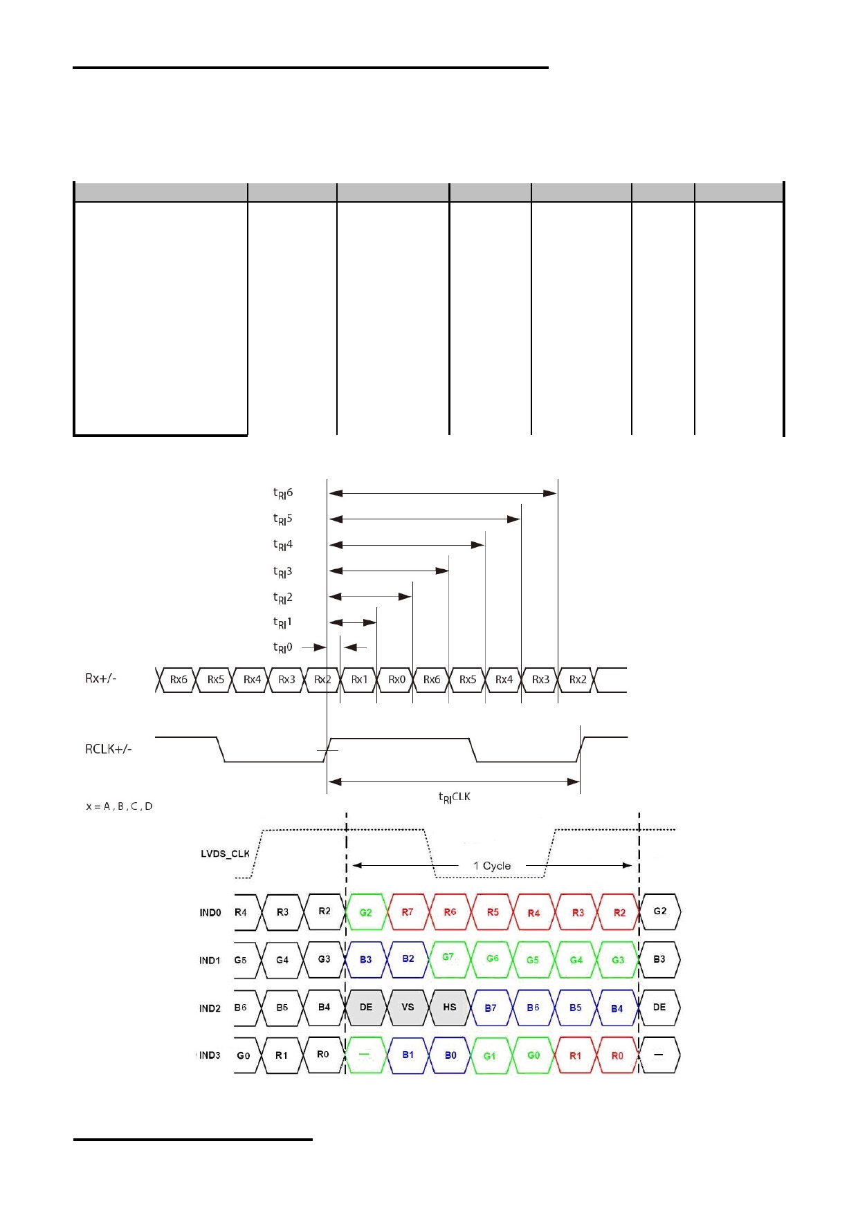
AC Characteristics(LVDS)
VDD=5.0V,GND=0V,T a =25 C
Item
Symbol
MIN.
TYP.
MAX.
Unit
Condition
Input CLK period
t RI CLK
8.9
-
50
ns
Input Data Position 0
t RI 0
-0.3
-
+0.3
ns
( tRICLK = 8.9ns )
Input Data Position 1
t RI 1
t RI CLK/7-0.3
t RI CLK/7
t RI CLK/7+0.3
ns
(tRICLK = 8.9ns )
Input Data Position 2
t RI 2
2t RI CLK/7-0.3
2t RI CLK/7
2t RI CLK/7+0.3
ns
(tRICLK = 8.9ns )
Input Data Position 3
t RI 3
3t RI CLK/7-0.3
3t RI CLK/7
3t RI CLK/7+0.3
ns
(tRICLK = 8.9ns )
Input Data Position 4
t RI 4
4t RI CLK/7-0.3
4t RI CLK/7
4t RI CLK/7+0.3
ns
(tRICLK = 8.9ns )
Input Data Position 5
t RI 5
5t RI CLK/7-0.3
5t RI CLK/7
5t RI CLK/7+0.3
ns
(tRICLK = 8.9ns )
Input Data Position 6
t RI 6
6t RI CLK/7-0.3
6t RI CLK/7
6t RI CLK/7+0.3
ns
(tRICLK = 8.9ns )
Input Clock and Data timing Diagram:
NURL: www.topwaydisplay.com
Document Name: LMK050DICFWD-AKA-Manual-Rev0.2
Page: 6 of 9
TOPWAY
LCD Module User Manual
LMK050DICFWD-AKA
6.2
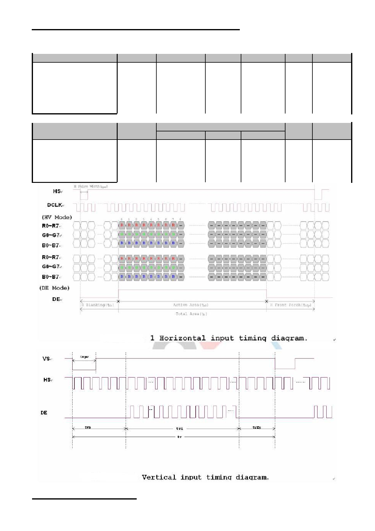
AC Characteristics(TFT)
Item
Symbol
MIN.
TYP.
MAX.
Unit
Remark
Horizontal Display Area
thd
-
800
-
DCLK
DCLK Frequency
fclk
26.4
33.3
46.8
MHz
One Horizontal Line
th
862
1056
1200
DCLK
HS pulse width
thpw
1
-
40
DCLK
HS Blanking
thb
46
46
46
DCLK
HS Front Porch
thfp
16
210
354
DCLK
Item
Symbol
Values
Unit
Remark
MIN.
TYP.
MAX.
Vertical Display Area
tvd
-
480
-
TH
VS period time
tv
510
525
650
TH
VS pulse width
tvpw
1
-
20
TH
VS Blanking
tvb
23
23
23
TH
VS Front Porch
tvfp
7
22
147
TH
NURL: www.topwaydisplay.com
Document Name: LMK050DICFWD-AKA-Manual-Rev0.2
Page: 7 of 9
TOPWAY
LCD Module User Manual
LMK050DICFWD-AKA
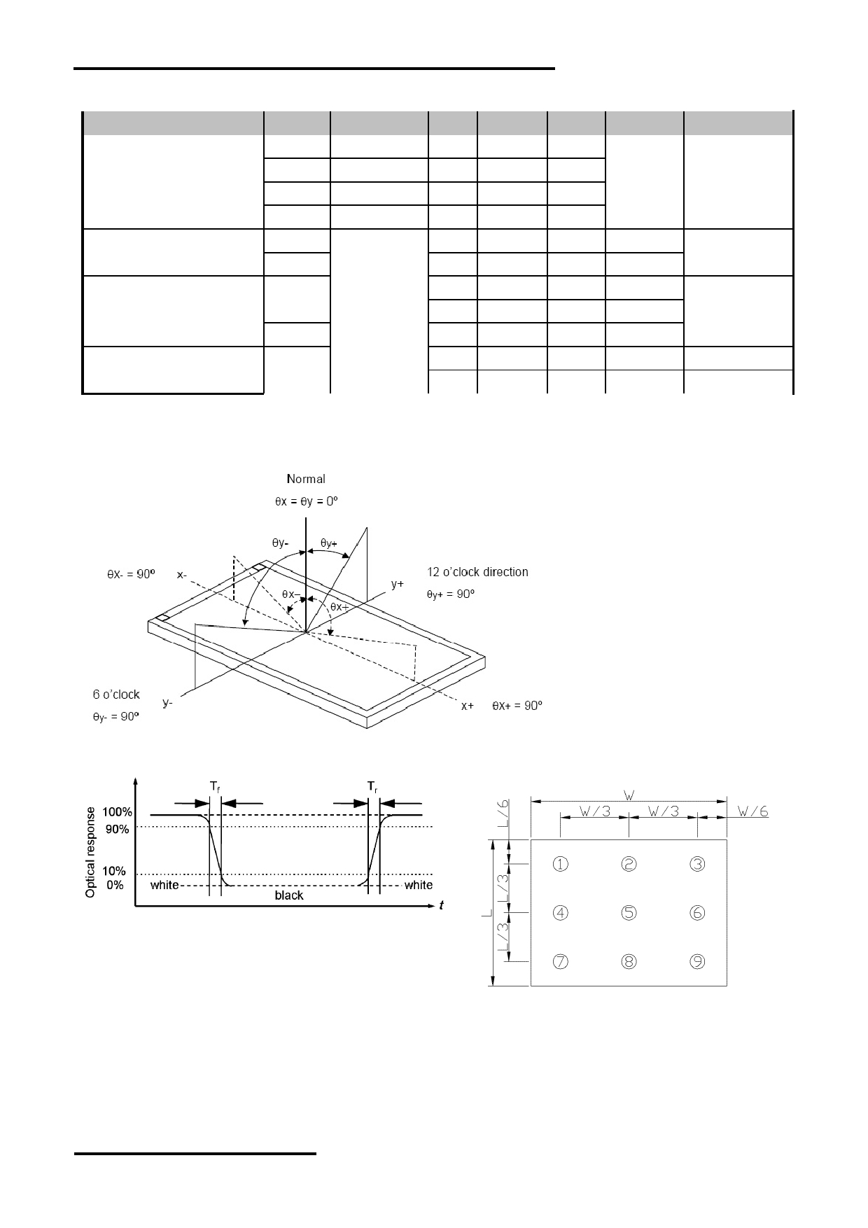
7. Optical Characteristics
Item
Symbol
Condition
MIN.
TYP.
MAX.
UNIT
Note.
θ L
9 o’clock
60
70
-
Viewing angle
θ R
3 o’clock
60
70
-
(CR ≥ 10)
degree
*2
θ T
12 o’clock
40
50
-
θ B
6 o’clock
60
70
-
T f
-
10
20
msec
Response Time
*3
T r
-
15
30
msec
Contrast ratio
CR
400
500
-
-
Normal
W X
0.26
0.31
0.26
-
*1
Color chromaticlty
θ=0 o
W Y
0.28
0.33
0.38
-
Luminance
L
-
500
-
cd/m 2
*4
Luminance uniformity
Y U
70
75
-
%
*4
Note:
*1. Definition of Contrast Ratio
The contrast ratio could be calculate by the following expression:
Contrast Ratio (CR) = Luminanc with all pixels white / Luminance with all pixels black
*2 Definition of Viewing Angle
*3 Definition of response time
*4 Definition of Luminance Uniformity
Luminance uniformity (Lu)=
Min. Luminance form pt1~pt9 / Max Luminance form Pt1~pt9
8. Precautions for Use of LCD Modules
Please refer to "LCD-Module-Design-Handling-Precaution.pdf".
NURL: www.topwaydisplay.com
Document Name: LMK050DICFWD-AKA-Manual-Rev0.2
Page: 8 of 9
TOPWAY
LCD Module User Manual
LMK050DICFWD-AKA
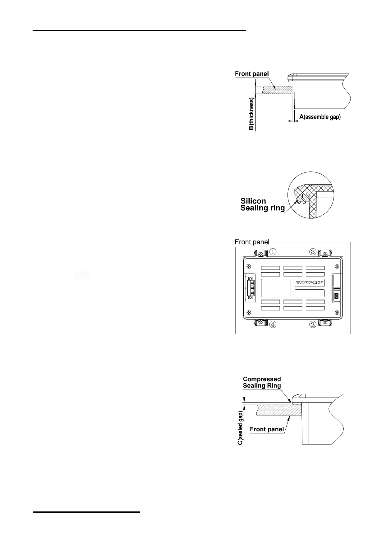
9 . Assemble Precaution
安装注意事项
1. Customer front panel opening and thickness for
TOPWAY display module should be fit for its assembling
and sealing.
The suggested assemble gap(A) should be about
0.3~0.5mm on each side.
The suggested front panel thickness(B) should be
about 1.5~4.0mm.
客户面板开窗及厚度应适合 TOPWAY 显示模块的安装及
密封 .
2. A silicon sealing ring ships with TOPWAY display
module. It should be in place before assembling to the
front panel.
TOPWAY 显示模块上的硅胶密封圈在安装时确保嵌入到
位 .
3. It should fix the TOPWAY display module into the front
panel with two steps.
Pre-fixing: Slightly tighten the screws on beam clamp
in sequence as picture on the right side.
Final-fixing: Tighten the fixing screws on beam clamp
in sequence as well with twist torque about 4~6kg.cm
(*1) . and put the beam clamp straight.
Note:
*1. Over tightening might damage the shell and cause bad sealing
result.
应分两步将 TOPWAY 显示模块固定在面板上 .
1), 并注意卡扣置正无歪斜 .
注 :
*1. 过度拧紧可能会损坏外壳和影响密封效果 .
4. It is strongly suggested to check the seal balancing of the
four-side of the TOPWAY display module.
The suggested after assemble sealed gap(C) should
be about 0.8~1.2mm.
需注意检查 TOPWAY 显示模块四周在安装后保证平衡密
封 .
5. Others:
Never hot plug the device! Power off the device before connect or disconnect the display
module.
Don't forget to remove the cover protective film for normal operation.
其它 :
NURL: www.topwaydisplay.com
Document Name: LMK050DICFWD-AKA-Manual-Rev0.2
Page: 9 of 9