LMT018DNBFWD-NDN
LCD Module User Manual
Prepared by:
Checked by:
Approved by:
Luo Lin
Date: 2017-08-10
Date:
Date:
Rev. Descriptions
Release Date
0.1
Preliminary New release
2017-08-10
URL: www.topwaydisplay.com
Document Name: LMT018DNBFWD-NDN--Manual-Rev0.1
Page: 1 of 13

LCD Module User Manual
LMT018DNBFWD-NDN
Table of Content
1. Basic Specifications .............................................................................................................. 3
1.1
Block Diagram ....................................................................................................................................... 3
1.2
K1/K2 Terminal Functions ..................................................................................................................... 4
2. Absolute Maximum Ratings .................................................................................................. 5
3. Electrical Characteristics ...................................................................................................... 5
3.1
DC Characteristics ................................................................................................................................. 5
3.2
LED Backlight Circuit Characteristics .................................................................................................... 5
3.3
AC Characteristics ................................................................................................................................. 6
4. Optical Characteristics .......................................................................................................... 7
5. Functions ............................................................................................................................... 9
5.1
Display Commands ................................................................................................................................ 9
5.2
Power off the LCD Module ................................................................................................................... 12
5.3
Refreshing The LCD Module ............................................................................................................... 12
6. Design and Handling Precaution ........................................................................................ 13
URL: www.topwaydisplay.com
Document Name: LMT018DNBFWD-NDN--Manual-Rev0.1
Page: 2 of 13
LCD Module User Manual
LMT018DNBFWD-NDN
1. Basic Specifications
Screen Size(Diagonal) :
1.8”
Color Depth:
65k / 262k color
Number of dots :
160 x 128 x 3(RGB)
Active Area :
35.04 x 28.032 mm
Dot Pitch :
0.219x0.219 mm
Display Technology :
a-Si TFT active matrix
Display Mode :
Transmissive / Positive
Pixel Configuration :
RGB Stripe
Viewing Direction :
9H (*1) (gray scale inverse)
3H (*2)
Polarizer Surface Treatment:
Glare
Backlight Type:
LEDs
Outline Dimension :
53.7 x 36.6 x 8.3(MAX.) mm
(see dwg for details)
Operating Temperature :
-20 ~ +70°C (No Condensation)
Storage Temperature :
-30 ~ +80°C (No Condensation)
note:
*1. For saturated color display content (eg. pure-red, pure-green, pure-blue, or pure-colors-combinations)
*2. For "color scales" display content
*3. Color tone may slightly change by Temperature and Driving Condition.
1.1 Block Diagram
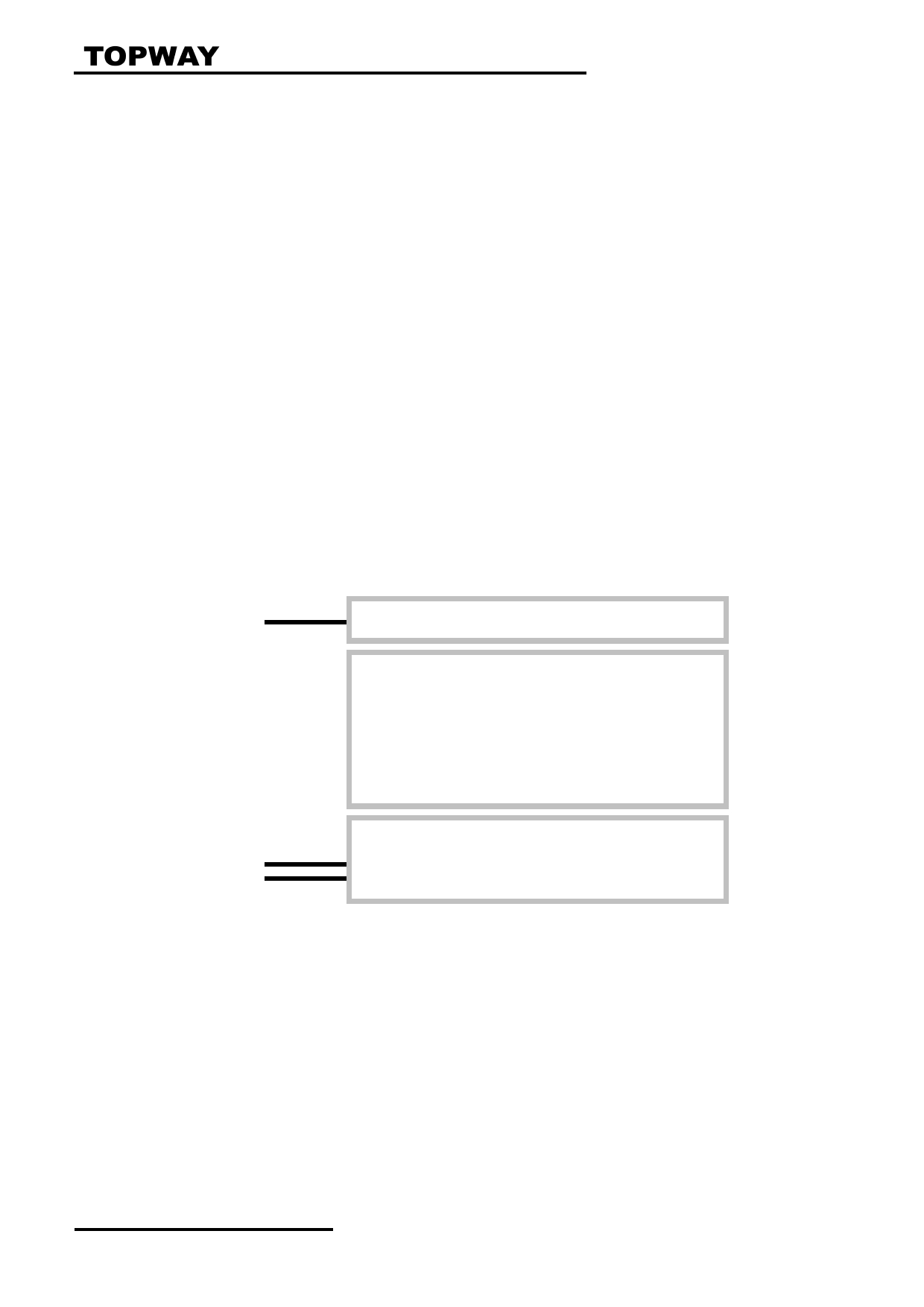
BLA, BLK
Backlight Circuit
TFT Panel
160 × 128(RGB)
VDD
VSS
/WR,/RD,DB0~DB7
ILI9163C or equivalent
/CS, /RES, D/C
URL: www.topwaydisplay.com
Document Name: LMT018DNBFWD-NDN--Manual-Rev0.1
Page: 3 of 13
LCD Module User Manual
LMT018DNBFWD-NDN
1.2 K1/K2 Terminal Functions
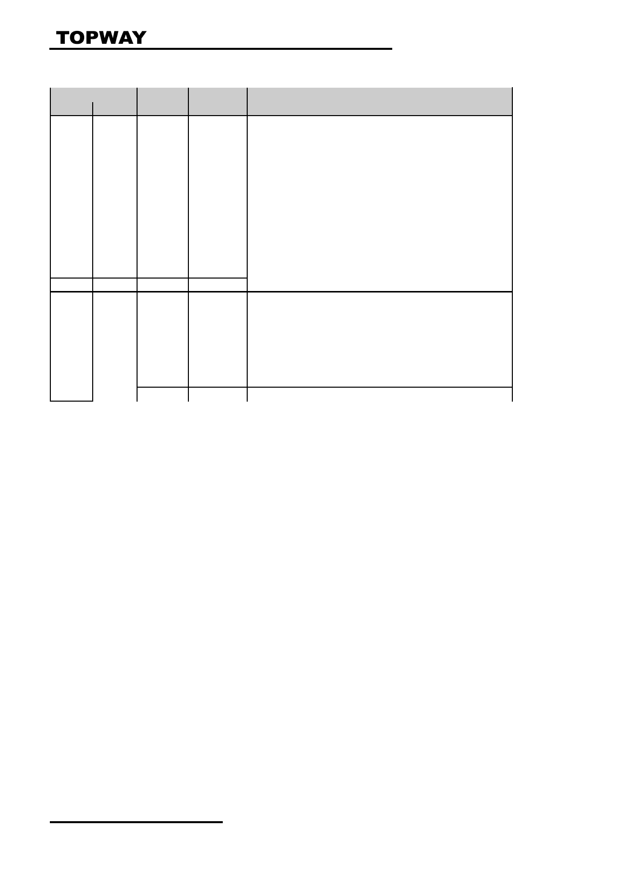
Pin No.
PIN
K1
K2
Name
I/O
Descriptions
1
7
/CS
Input
Chip Select
/CS=L, enable access to the LCD module
/CS=H, disable access to the LCD module
2
8
/RES
Input
Reset signal
/RES = L, Initialization is executed
/RES = H, Normal running.
3
9
D/C
Input
Register Select
D/C = H, Transferring the Display Data
D/C = L, Transferring the Control Data
4
10
/WR
Input
Write enable input, active LOW
5
11
/RD
Input
Read enable input, active LOW
6
19
D0
IO
Bi-directional tri-state Data bus
:
:
:
13
12
D7
IO
14
4
VDD
Power
Positive power supply
15
3,20
VSS
Power
Negative power supply,0V
16
2
BLA
Power
Positive power for LED backlight
17
1
BLK
Power
Negative power for LED backlight
18
5
NC
-
No connection leave open
19
6
NC
-
No connection leave open
:
:
:
32
NC
-
No connection leave open
URL: www.topwaydisplay.com
Document Name: LMT018DNBFWD-NDN--Manual-Rev0.1
Page: 4 of 13

LCD Module User Manual
LMT018DNBFWD-NDN
2. Absolute Maximum Ratings
Items
Symbol
Min.
Max.
Unit Condition
Supply Voltage
V DD
-0.3
+4.6
V
V SS = 0V
Input Voltage
V IN
-0.3
+4.6
V
V SS = 0V
Operating Temperature
T OP
-20
+70
C
No Condensation
Storage Temperature
T ST
-30
+80
C
No Condensation
Cautions:
Any Stresses exceeding the Absolute Maximum Ratings may cause substantial damage to the device. Functional
operation of this device at other conditions beyond those listed in the specification is not implied and prolonged exposure
to extreme conditions may affect device reliability.
3. Electrical Characteristics
3.1 DC Characteristics
V SS =0V, V DD =2.8V, T OP =25 C
Items
Symbol
MIN.
TYP.
MAX.
Unit Condition /
Application Pin
Operating Voltage
V DD
2.6
2.8
3.3
V
VDD
Input High Voltage
V IH
0.8xV DD
-
V DD
V
/RES, /CS, D/C,
Input Low Voltage
V IL
V SS
-
0.2xV DD
V
DB0~DB7,/WR,/RD
Operating Current
I DD
-
1.2
3.5
mA VDD (*1)
Note: *1. V DD =2.8V
3.2 LED Backlight Circuit Characteristics
BLK=0V, If BLA =30mA, T OP =25 C
Items
Symbol
MIN.
TYP.
MAX.
Unit
Applicable Pin
Forward Voltage
Vf BLA
-
3.2
-
V
BLA
Forward Current
If BLA
-
30
-
mA
BLA
Color Coordinate
X
0.270
-
0.315
-
(White)
Y
0.270
-
0.315
-
Uniformity
∆Bp
80%
-
-
-
Cautions:
Exceeding the recommended driving current could cause substantial damage to the backlight and shorten its lifetime.
BLA
BLK
No. of LEDs = 2pcs
URL: www.topwaydisplay.com
Document Name: LMT018DNBFWD-NDN--Manual-Rev0.1
Page: 5 of 13
LCD Module User Manual
LMT018DNBFWD-NDN
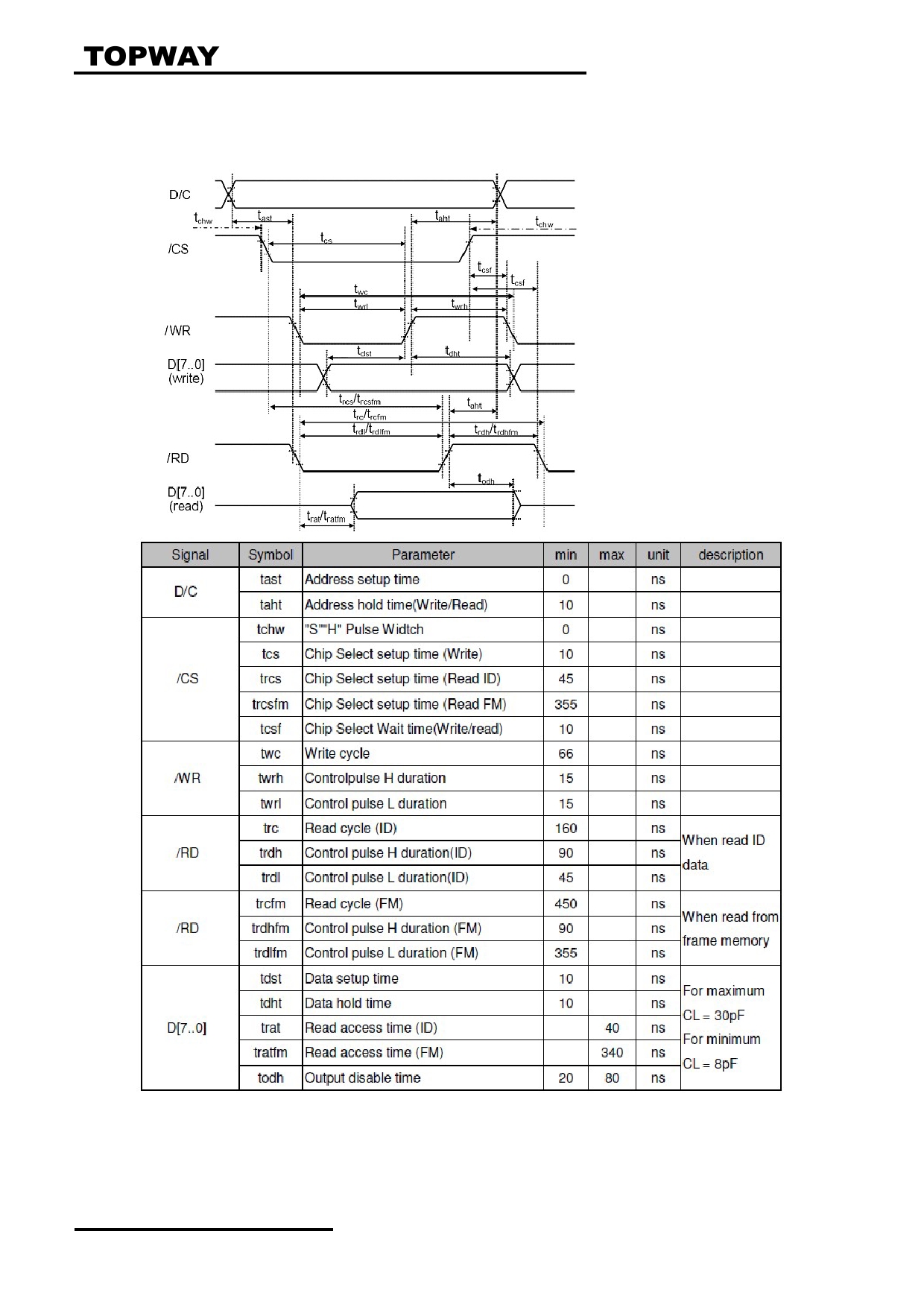
3.3 AC Characteristics
8080 Mode System Bus Timing
V SS =0V, V DD =2.8V, T OP =25 C
Note:
*1. Input signal rise/fall time should be less than 15ns .
*2. All timing is using 20% and 80% of VDD as the reference.
*3. Please refer to ILI9163C datasheet for details
URL: www.topwaydisplay.com
Document Name: LMT018DNBFWD-NDN--Manual-Rev0.1
Page: 6 of 13
LCD Module User Manual
LMT018DNBFWD-NDN
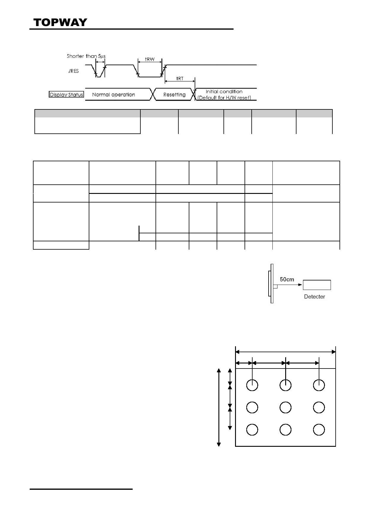
Reset Timing
V SS =0V, V DD =2.8V, T OP =25 C
Item
Symbol
MIN.
TYP.
MAX.
Unit
Reset LOW pulse width
t RW
1.0
-
-
us
Reset time
T RT
-
-
120
ms
4. Optical Characteristics
Item
Symbol
Min.
Typ.
Max.
Unit
Note/ Condition
Brightness
Bp
190
-
-
Cd/m 2
θ =0°, Φ =0° (*1,*2)
Uniformity
△ Bp
80%
-
-
-
Viewing Angle
θ 1( Ф =90°or 270°)
-50 ~ +40
Deg
(*3)
θ 2( Ф =0° or 180°)
-50 ~ +50
deg
Contrast
Cr
-
-
350
-
θ =0°, Φ =0° (*4)
Ratio
Response Time
T r+ +T f
-
30
-
Ms
θ =0°, Φ =0° (*5)
Color of CIE
W
X
0.246
0.296
0.346
θ =0°, Φ =0° (*1, *6)
Coordinate
Y
0.265
0.315
0.365
NTSC Ratio
S
42%
-
-
-
θ =0°, Φ =0° (*1, *6)
Note:
*1. Measurement
The data are measured after LEDs are turned on for 5 minutes. LCM
displays full white. The brightness is the average value of 9 measured
spots.
Measurement equipment PR-705 (Φ8mm)
Measuring condition:
- Measuring surroundings: Dark room.
- Measuring temperature: Ta=25 ℃ .
- Adjust operating voltage to get optimum contrast at the center of the display.
Measured value at the center point of LCD panel after more than 5 minutes while backlight turning on.
*2. The luminance uniformity
W
It is calculated by using following formula.
2W
3W
3W
△ Bp = Bp (Min.) / Bp (Max.)×100 (%)
Bp (Max.) = Maximum brightness in 9 measured spots
Bp (Min.) = Minimum brightness in 9 measured spots.
Measurement equipment PR-705 (Φ8mm)
URL: www.topwaydisplay.com
Document Name: LMT018DNBFWD-NDN--Manual-Rev0.1
Page: 7 of 13
LCD Module User Manual
LMT018DNBFWD-NDN
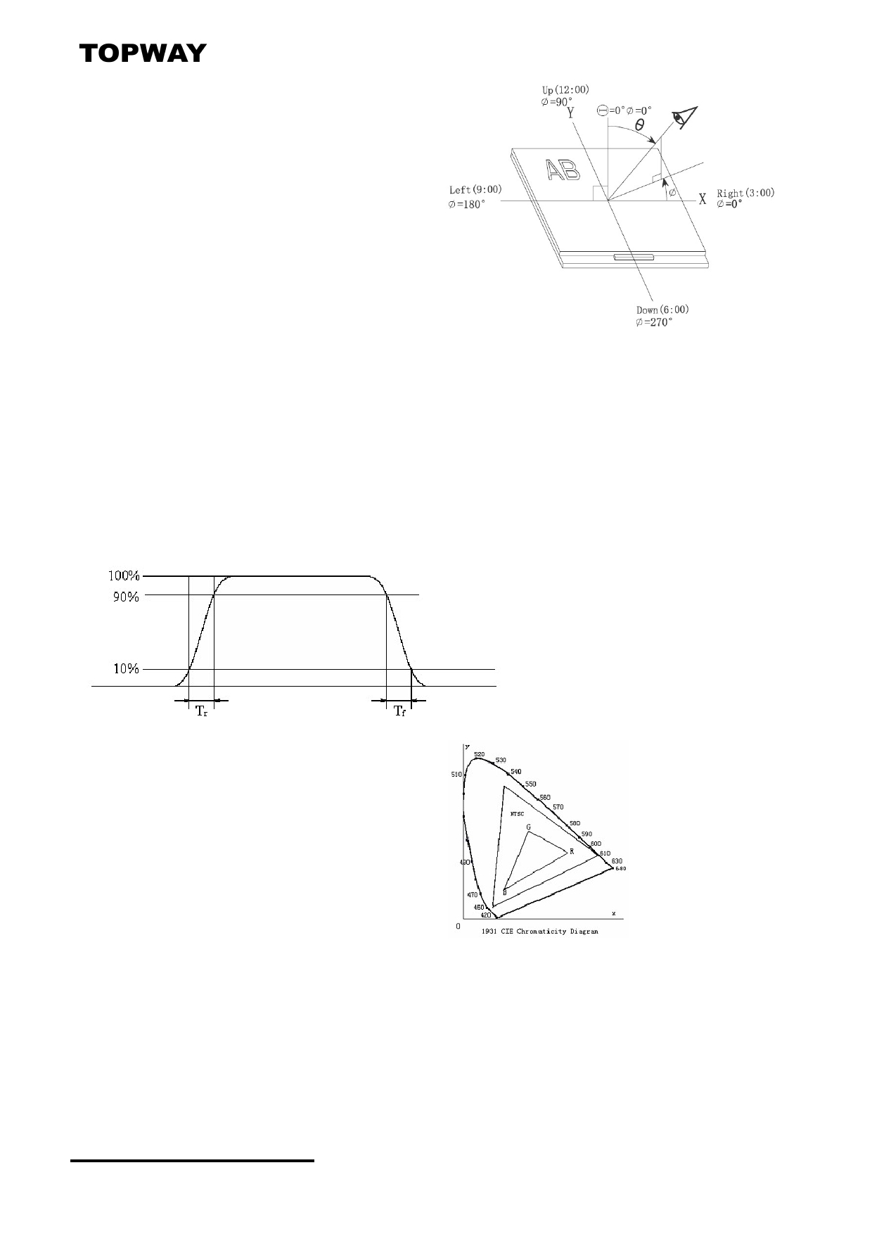
*3. The definition of viewing angle:
Refer to the graph below marked by θ and Ф
*4. The definition of contrast ratio (Test LCM using PR-705):
Contrast Ratio(CR)=
Luminance When LCD is at “White” state
Luminance When LCD is at “Black” state
(Contrast Ratio is measured in optimum common electrode voltage)
*5. Definition of Response time.(Test LCD using DMS501):
The output signals of photo detector are measured when the input signals are changed
from “black” to “white”(falling time) and from “white” to “black”(rising time), respectively.
The response time is defined as the time interval between the 10% and 90% of
amplitudes. Refer to figure as below.
*6: Definition of Color of CIE Coordinate and
NTSC Ratio.
S=
area of RGB triangle
area of NTSC triangle
x100%
URL: www.topwaydisplay.com
Document Name: LMT018DNBFWD-NDN--Manual-Rev0.1
Page: 8 of 13
LCD Module User Manual
LMT018DNBFWD-NDN
5. Functions
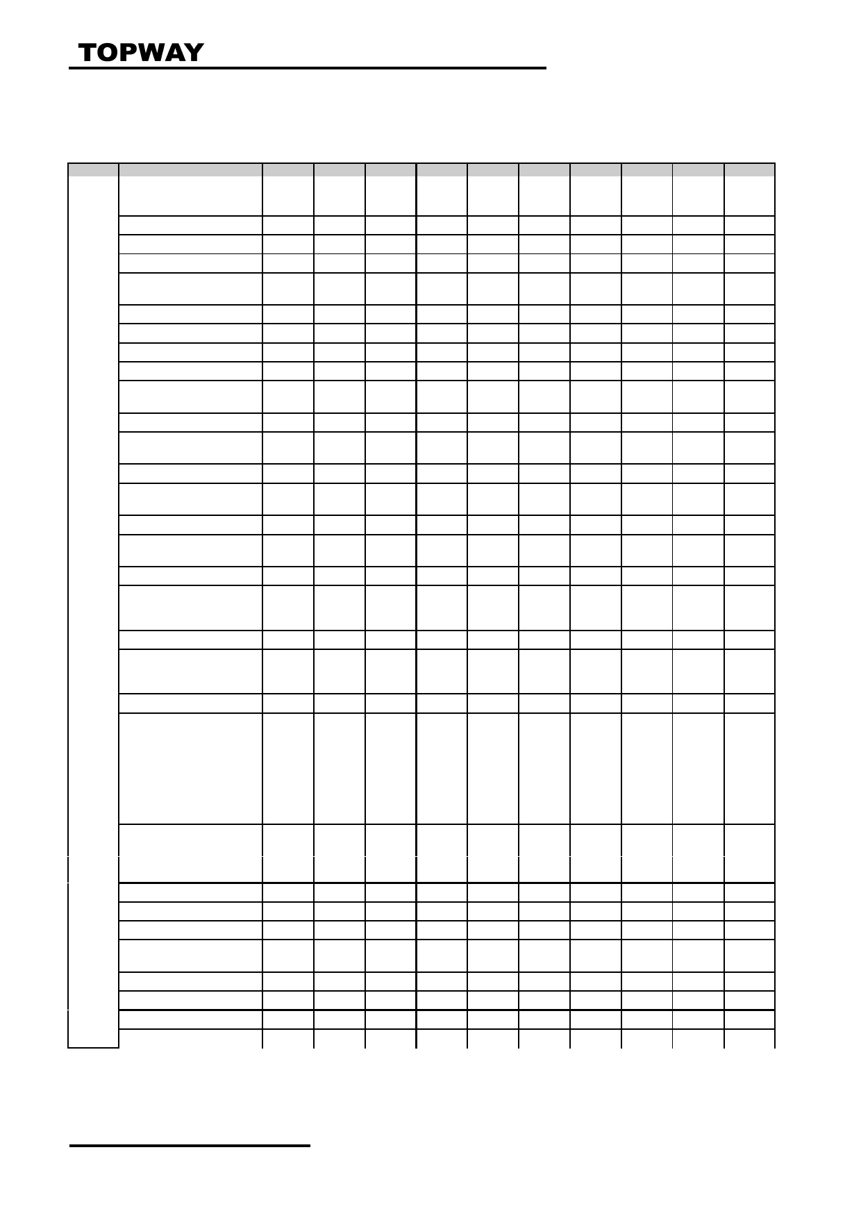
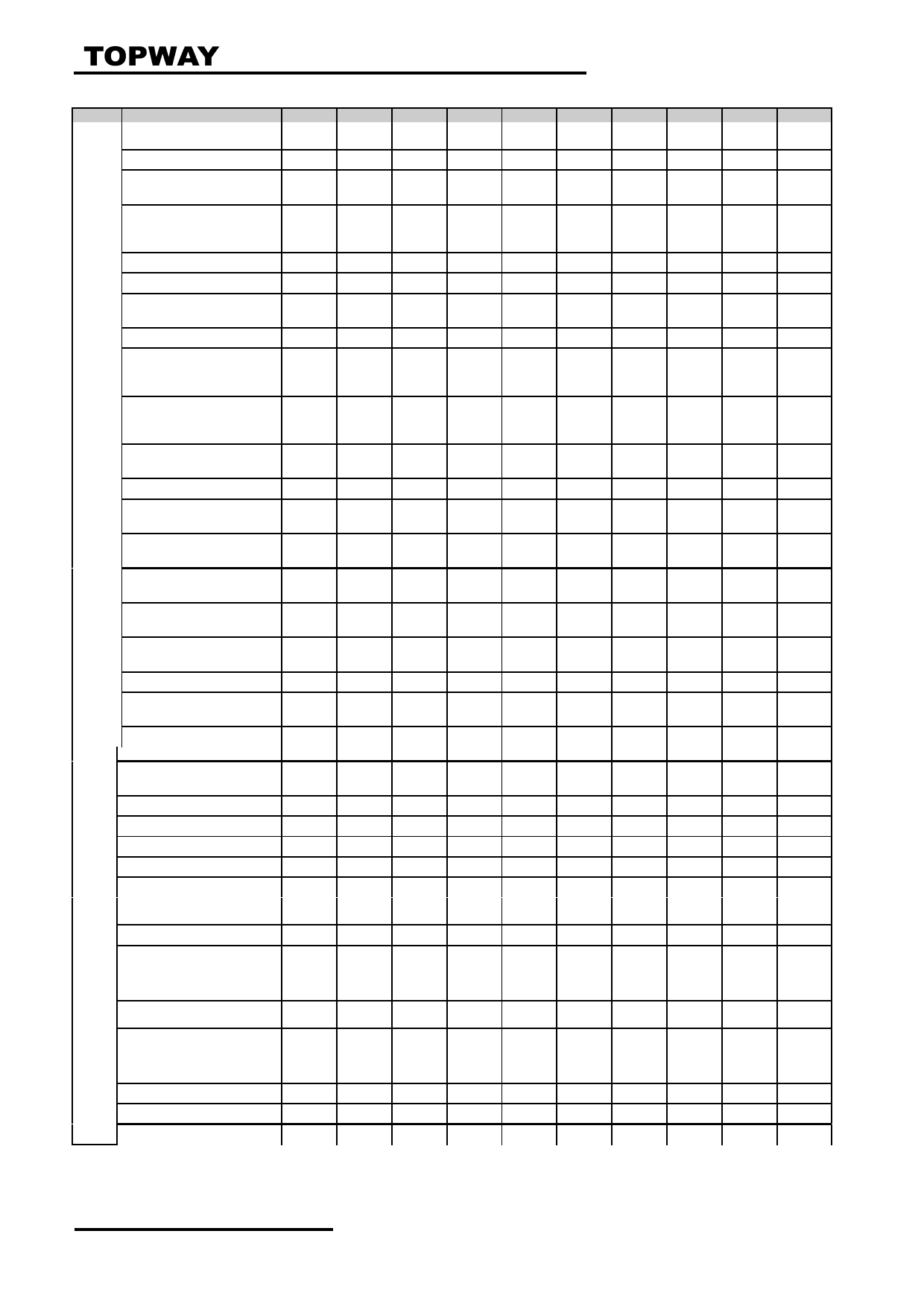
5.1 Display Commands
Code Command
D17-D8
D7
D6
D5
D4
D3
D2
D1
D0
hex
00H
NOP (No Operation)
X
0
0
0
0
0
0
0
0
00h
01H
SoftwareReset
X
0
0
0
0
0
0
0
1
01h
04H
Read Display Id. Info
x
0
0
0
0
0
1
0
0
04h
1 Parameter
st
x
x
x
x
x
x
x
x
x
x
2
nd
Parameter
x
ID17
ID16
ID15
ID14
ID13
ID12
ID11
ID10
54h
3 Parameter
rd
x
ID27
ID26
ID25
ID24
ID23
ID22
ID21
ID20
80h
4 Parameter
th
x
ID37
ID36
ID35
ID34
ID33
ID32
ID31
ID30
66h
09H
Read Display Status
x
0
0
0
0
1
0
0
1
09h
1 Parameter
st
x
x
x
x
x
x
x
x
x
x
2
nd
Parameter
x
BOTSON
MY
MX
MV
ML
RGB
MH
ST24
00h
3 Parameter
rd
x
ST23
IFPF2
IFPF1
IFPF0
IDMON PTLON SLOUT NORON
61h
4 Parameter
th
x
VSSON
ST14
INVON
ST12
ST11
DISON
TEON
GCS2
00h
5 Parameter
th
x
GCS1
GCS0
TELOM
HSON
VSON
PCKON
DEON
ST0
00h
0AH
Read Display Power Mode
x
0
0
0
0
1
0
1
0
0Ah
1 Parameter
st
x
x
x
x
x
x
x
x
x
X
2
nd
Parameter
x
BSTON IDMON PLTON SLPOUT NORON DISON
D1
D0
08h
0BH
Read Display MADCTL
x
0
0
0
0
1
0
1
1
0Bh
1 Parameter
st
x
x
x
x
x
x
x
x
x
X
2
nd
Parameter
x
MY
MX
MV
ML
RGB
MH
D1
D0
00h
0CH
Read Display Pixel Format
x
0
0
0
0
1
1
0
0
0Ch
1 Parameter
st
x
x
x
x
x
x
x
x
x
x
2
nd
Parameter
x
VIPF3
VIPF2
VIPF1
VIPF0
D3
IFPF2
IFPF1
IFPF0
06h
0DH
Read Display Image Mode
x
0
0
0
0
1
1
0
1
0Dh
1 Parameter
st
x
x
x
x
x
x
x
x
x
x
2
nd
Parameter
x
VSSON
D6
INVON
D4
D3
GCS2
GCS1
GCS0
00h
0EH
Read Display
x
0
0
0
0
1
1
1
0
0Eh
Signal Mode
1 Parameter
st
x
x
x
x
x
x
x
x
x
x
2
nd
Parameter
x
D7
D6
HSON
VSON
PCKON DEON
D1
D0
00h
0FH
Read Display
x
0
0
0
0
1
1
1
1
0Fh
Signal Mode
1 Parameter
st
x
x
x
x
x
x
x
x
x
x
2
nd
Parameter
x
RELD
FUND
D5
D4
D3
D2
D1
D0
00h
10H
Sleep In
x
0
0
0
1
0
0
0
0
10h
11H
Sleep Out
x
0
0
0
1
0
0
0
1
11h
12H
Partial Mode On
x
0
0
0
1
0
0
1
0
12h
13H
Normal Display Mode On
x
0
0
0
1
0
0
1
1
13h
20H
Display Inversion Off
x
0
0
1
0
0
0
0
0
20h
21H
Display Inversion On
x
0
0
1
0
0
0
0
1
21h
26H
Gamma Set
x
0
0
1
0
0
1
1
0
26h
1 Parameter
st
x
GC7
GC6
GC5
GC4
GC3
GC2
GC1
GC0
01h
28H
Display Off
0
0
1
0
1
0
0
0
28h
29H
Display On
x
0
0
1
0
1
0
0
1
29h
2AH
Column Address Set
x
0
0
1
0
1
0
1
0
2Ah
1 Parameter
st
x
XS15
XS14
XS13
XS12
XS11
XS10
XS9
XS8
-
2
nd
Parameter
x
XS7
XS6
XS5
XS4
XS3
XS2
XS1
XS0
-
3 Parameter
rd
x
XE15
XE14
XE13
XE12
XE11
XE10
XE9
XE8
-
4 Parameter
th
x
XE7
XE6
XE5
XE4
XE3
XE2
XE1
XE0
-
2BH Page Address Set
x
0
0
1
0
1
0
1
1
2Bh
1 Parameter
st
x
YS15
YS14
YS13
YS12
YS11
YS10
YS9
YS8
-
2
nd
Parameter
x
YS7
YS6
YS5
YS4
YS3
YS2
YS1
YS0
-
3 Parameter
rd
x
YE15
YE14
YE13
YE12
YE11
YE10
YE9
YE8
-
4 Parameter
th
x
YE7
YE6
YE5
YE4
YE3
YE2
YE1
YE0
-
URL: www.topwaydisplay.com
Document Name: LMT018DNBFWD-NDN--Manual-Rev0.1
Page: 9 of 13

LCD Module User Manual
LMT018DNBFWD-NDN
Code Command
D17-D8
D7
D6
D5
D4
D3
D2
D1
D0
hex
2CH
Memory Write
x
0
0
1
0
1
1
0
0
2Ch
1 Parameter
st
D17-8
D7
D6
D5
D4
D3
D2
D1
D0
-
:
x
:
:
:
:
:
:
:
:
:
N Parameter
th
D17-8
D7
D6
D5
D4
D3
D2
D1
D0
-
2DH
Color Setting for 4K,
x
0
0
1
0
1
1
0
1
2Dh
65Kand 262K
1 Parameter
st
x
x
x
R005
R004
R003
R002
R001
R000
-
:
x
x
x
Rnn5
Rnn4
Rnn3
Rnn2
Rnn1
Rnn0
-
32
nd
parameter
x
x
x
R315
R314
R313
R312
R311
R310
-
33 Parameter
rd
x
x
x
G005
G004
G003
G002
G001
G000
-
:
x
x
x
Gnn5
Gnn4
Gnn3
Gnn2
Gnn1
Gnn0
-
96 Parameter
th
x
x
x
G635
G634
G633
G632
G631
G630
-
97 Parameter
th
x
x
x
B005
B004
B003
B002
B001
B000
:
x
x
x
Bnn5
Bnn4
Bnn3
Bnn2
Bnn1
Bnn0
-
128 Parameter
th
x
x
x
B315
B314
B313
B312
B311
B310
-
2EH
Memory Read
x
0
0
1
0
1
1
1
0
2Eh
1 Parameter
st
x
x
x
x
x
x
x
x
x
-
2
nd
Parameter
x
D17
D16
D15
D14
D13
D12
D11
D10
-
:
x
-
N Parameter
th
x
Dn7
Dn6
Dn5
Dn4
Dn3
Dn2
Dn1
Dn0
-
30H
Partial Area
x
0
0
1
1
0
0
0
0
30h
1 Parameter
st
x
PSL15
PSL14
PSL13
PSL12
PSL11
PSL10
PSL9
PSL8
-
2
nd
Parameter
x
PSL7
PSL6
PSL5
PSL4
PSL3
PSL2
PSL1
PSL0
-
3 Parameter
rd
x
PEL15
PEL14
PEL13
PEL12
PEL11
PEL10
PEL9
PEL8
-
4 Parameter
th
x
PEL7
PEL6
PEL5
PEL4
PEL3
PEL2
PEL1
PEL0
-
33H
Vertical Scrolling
x
0
0
1
1
0
0
1
1
33h
Definition
1 Parameter
st
x
TFA15
TFA14
TFA13
TFA12
TFA11
TFA10
TFA9
TFA8
-
2
nd
Parameter
x
TFA7
TFA6
TFA5
TFA4
TFA3
TFA2
TFA1
TFA0
-
3 Parameter
rd
x
VSA15
VSA14
VSA13
VSA12
VSA11
VSA10
VSA9
VSA8
-
4 Parameter
th
x
VSA7
VSA6
VSA5
VSA4
VSA3
VSA2
VSA1
VSA0
-
5 Parameter
th
x
BFA15
BFA14
BFA13
BFA12
BFA11
BFA10
BFA9
BFA8
-
6 Parameter
th
x
BFA7
BFA6
BFA5
BFA4
BFA3
BFA2
BFA1
BFA0
-
34H
Tearing EffectLine Off
x
0
0
1
1
0
1
0
0
34h
35H
Tearing EffectLine On
x
0
0
1
1
0
1
0
1
35h
1 Parameter
st
x
x
x
x
x
x
x
x
M
00h
36H
Memory Access Control
x
0
0
1
1
0
1
1
0
36h
1 Parameter
st
x
MY
MX
MV
ML
RGB
MH
x
x
00h
37H
VerticalScrolling
x
0
0
1
1
0
1
1
1
37h
StartAddress
1 Parameter
st
x
SSA15
SSA14
SSA13
SSA12
SSA11
SSA10
SSA9
SSA8
00h
2
nd
Parameter
x
SSA7
SSA6
SSA5
SSA4
SSA3
SSA2
SSA1
SSA0
00h
38H
Idle Mode Off
x
0
0
1
1
1
0
0
0
38h
39H
Idle Mode On
x
0
0
1
1
1
0
0
1
39h
3AH
Interface PixelFormat
x
0
0
1
1
1
0
1
0
3Ah
1 Parameter
st
x
VIPF3
VIPF2
VIPF1
VIPF0
D3
IFPF2
IFPF1
IFPF0
66h
B1H
Frame Rate Control
1
0
1
1
0
0
0
1
B1h
(In normal mode/Full
colors)
1 Parameter
st
x
x
x
DIVA4
DIVA3
DIVA2
DIVA1
DIVA0
x
2
nd
Parameter
x
x
VPA5
VPA4
VPA3
VPA2
VPA1
VPA0
x
B2H
Frame Rate Control
1
0
1
1
0
0
1
0
B2h
(In Idle mode/8-colors)
1 Parameter
st
x
x
x
DIVB4
DIVB3
DIVB2
DIVB1
DIVB0
x
2
nd
Parameter
x
x
VPB5
VPB4
VPB3
VPB2
VPB1
VPB0
x
URL: www.topwaydisplay.com
Document Name: LMT018DNBFWD-NDN--Manual-Rev0.1
Page: 10 of 13
LCD Module User Manual
LMT018DNBFWD-NDN
Code Command
D17-D8
D7
D6
D5
D4
D3
D2
D1
D0
hex
B3H Frame Rate Control
1
0
1
1
0
0
1
1
B3h
(In Partial mode/full colors)
1 Parameter
st
x
x
x
DIVC4
DIVC3
DIVC2
DIVC1
DIVC0
x
2
nd
Parameter
x
x
VPC5
VPC4
VPC3
VPC2
VPC1
VPC0
x
B4H Display Inversion Control
x
1
0
1
1
0
1
0
0
B4h
1 Parameter
st
x
0
0
0
0
0
NLA
NLB
NLC
02H
B5H RGB Interface Blanking
x
1
0
1
1
0
1
0
1
B5h
Porch setting
1 Parameter
st
x
x
x
HBP5
HBP4
HBP3
HBP2
HBP1
HBP0
08h
2
nd
Parameter
x
VBP7
VBP6
VBP5
VBP4
VBP3
VBP2
VBP1
VBP0
03h
3 Parameter
rd
x
x
x
x
x
x
x
VBP9
VBP8
00h
B6H Display Function Set
x
1
0
1
1
0
1
1
0
B6h
1 Parameter
st
x
x
NO1
NO0
SDT1
SDT0
EQ1
EQ2
06h
2
nd
Parameter
x
x
x
X
x
PTG0
PT1
PT0
02h
B7H Source Driver Direction
x
1
0
1
1
0
1
1
1
B7h
Control
1 Parameter
st
x
0
0
0
0
0
0
0
CRL
00h
B8H Gate Driver Direction
x
1
0
1
1
1
0
0
0
B8h
Control
1 Parameter
st
x
0
0
0
0
0
0
0
CTB
00h
C0H Power_ Control1
x
1
1
0
0
0
0
0
0
C0h
1 Parameter
st
x
0
0
0
VRH4
VRH3
VRH2
VRH1
VRH0
x
2
nd
Parameter
x
0
0
0
0
0
VC2
VC1
VC0
02h
C1H Power_ Control2
x
1
1
0
0
0
0
0
1
C1h
1 Parameter
st
x
0
0
0
0
0
BT2
BT1
BT0
07h
C2H Power_ Control3
x
1
1
0
0
0
0
1
0
C2h
1 Parameter
st
x
0
0
0
0
0
APA2
APA1
APA0
00h
C3H Power_ Control4
x
1
1
0
0
0
0
1
1
C3h
1 Parameter
st
x
0
0
0
0
0
APB2
APB1
APB0
00h
C4H Power_ Control 5
x
1
1
0
0
0
1
0
0
C4h
1 Parameter
st
x
0
0
0
0
0
APC2
APC1
APC1
01h
C5H VCOM_ Control 1
x
1
1
0
0
0
1
0
1
C5h
1 Parameter
st
x
x
VMH6
VMH5
VMH4
VMH3
VMH2
VMH1
VMH0
-
2
nd
Parameter
x
0
VML6
VML5
VML4
VML3
VML2
VML1
VML0
-
C6H VCOM_ Control 2
x
1
1
0
0
0
1
1
0
C6h
1 Parameter
st
x
0
0
VMA5
VMA4
VMA3
VMA2
VMA1
VMA0
13h/06h
C7H VCOM OffsetControl
x
1
1
0
0
0
1
1
1
C7h
1 Parameter
st
0
nVM*
VMF6
VMF5
VMF4
VMF3
VMF2
VMF1
VMF0
40h
D3H Write ID4Value
x
1
1
0
1
0
0
1
1
D3h
1 Parameter
st
x
x
x
x
x
x
x
x
x
x
2
nd
Parameter
x
ID417
ID416
ID415
ID414
ID413
ID412
ID411
ID410
91h
3 Parameter
rd
x
ID427
ID426
ID425
ID424
ID423
ID422
ID421
ID420
63h
4 Parameter
th
x
x
x
x
x
ID433
ID432
ID431
ID430
00h
5 Parameter
th
x
x
x
x
x
x
x
x
x
x
D5H NV Memory Function
x
1
1
0
1
1
0
1
0
D5h
Controller(1)
1 Parameter
st
x
ID33
ID32
ID31
ID30
ID23
ID22
ID21
ID20
00h
2
nd
Parameter
x
OTP_ BS
0
0
0
OTP_
OTP_
OTP_
OTP_
00h
VMF3
VMF2
VMF1
VMF0
D6H NV Memory Function
x
1
1
0
1
1
0
1
0
D6h
Controller(2)
1 Parameter
st
x
OTP_D[7 OTP_
OTP_
OTP_
OTP_
OTP_
OTP_
OTP_
00h
]
D[6]
D[5]
D[4]
D[3]
D[2]
D[1]
D[0]
2
nd
Parameter
x
0
0
0
0
0
0
OTP_
OTP_
00h
TP[1]
TP[0]
D7H NV Memory Function
x
1
1
0
1
1
0
1
0
D7h
Controller(3)
1 Parameter
st
x
0
1
0
1
0
1
0
1
55h
2
nd
Parameter
x
1
0
1
0
1
0
1
0
AAh
3 Parameter
rd
x
0
1
1
0
0
1
1
0
66h
URL: www.topwaydisplay.com
Document Name: LMT018DNBFWD-NDN--Manual-Rev0.1
Page: 11 of 13
LCD Module User Manual
LMT018DNBFWD-NDN
Code Command
D17-D8
D7
D6
D5
D4
D3
D2
D1
D0
hex
DAH Read ID1
x
1
1
0
1
1
0
1
0
DAh
1 Parameter
st
x
x
x
x
x
x
x
x
x
x
2
nd
Parameter
x
ID17
ID16
ID15
ID14
ID13
ID12
ID11
ID10
54h
DBH Read ID2
x
1
1
0
1
1
0
1
1
DBh
1 Parameter
st
x
x
x
x
x
x
x
x
x
x
2
nd
Parameter
x
1
ID26
ID25
ID24
ID23
ID22
ID21
ID20
80h
DCH Read ID3
x
1
1
0
1
1
1
0
0
DCh
1 Parameter
st
x
x
x
x
x
x
x
x
x
x
2
nd
Parameter
x
ID37
ID36
ID35
ID34
ID33
ID32
ID31
ID30
66h
E0H Positive Gamma
1
1
1
0
0
0
0
0
E0h
Correction Setting
1 Parameter
st
x
x
VP0[5:0]
-
2
nd
Parameter
x
x
VP1[5:0]
-
3 Parameter
rd
x
x
VP2[5:0]
-
4 Parameter
th
x
x
VP4[5:0]
-
5 Parameter
th
x
x
VP6[5:0]
-
6 Parameter
th
x
x
x
VP13[4:0]
-
7 Parameter
th
x
VP20[6:0]
-
8 Parameter
th
VP36[3:0]
VP27[3:0]
-
9 Parameter
th
x
VP43[6:0]
-
10 Parameter
th
x
VP50[5:0]
-
11 Parameter
st
x
x
VP57[5:0]
-
12
nd
arameter
x
x
VP59[5:0]
-
13 Parameter
rd
x
x
VP61[5:0]
-
14 Parameter
th
x
x
VP62[5:0]
-
15 Parameter
th
x
x
VP63[5:0]
-
E1H Negative Gamma
1
1
1
0
0
0
0
1
E1h
Correction Setting
1 Parameter
st
x
x
VN63[5:0]
-
2
nd
Parameter
x
x
VN62[5:0]
-
3 Parameter
rd
x
x
VN61[5:0]
-
4 Parameter
th
x
x
V59[5:0]
-
5 Parameter
th
x
x
VN57[5:0]
-
6 Parameter
th
x
x
x
VN50[4:0]
7 Parameter
th
x
x
VN43[6:0]
-
8 Parameter
th
VN27[3:0]
VN36[3:0]
-
9 Parameter
th
x
VN20[6:0]
-
10 Parameter
th
x
x
VN13[5:0]
-
11 Parameter
st
x
x
VN6[5:0]
-
12
nd
arameter
x
x
VN4[5:0]
-
13 Parameter
rd
x
x
VN2[5:0]
-
14 Parameter
th
x
x
VN1[5:0]
-
15 Parameter
th
x
x
VN0[5:0]
-
F2H GAM_R_SEL
1
1
1
1
0
0
1
0
F2h
1 Parameter
st
x
x
x
x
x
x
x
GAM_R_ Write
SEL
Notes:
1. There will be no abnormal visible effects on the display when S/W or H/W Reset are applied.
2. After Powered-On Reset finishes within 10%s after both VDD & VDDI are applied.
3. Mode 1 means Tearing Effect Output Line consists of V-Blanking Information only.
4.
Please refer to ILI9163C datasheet for details
5.2 Power off the LCD Module
It recommends that enter Sleep Mode before power off the LCD module.
5.3 Refreshing The LCD Module
It recommends that the operating modes and display contents be refreshed periodically to prevent
the effect of unexpected noise.
URL: www.topwaydisplay.com
Document Name: LMT018DNBFWD-NDN--Manual-Rev0.1
Page: 12 of 13

LCD Module User Manual
LMT018DNBFWD-NDN
6. Design and Handling Precaution
Please refer to "LCD-Module-Design-Handling-Precaution.pdf".
URL: www.topwaydisplay.com
Document Name: LMT018DNBFWD-NDN--Manual-Rev0.1
Page: 13 of 13