LMT070DICFWD-AKE
LCD Module User Manual
Prepared by:
Checked by:
Approved by:
YU
Date: 2019-07-16
Date:
Date:
Rev. Descriptions
Release Date
0.1
Preliminary
2019-07-16
0.2
Revise indicator definition
2019-09-26
0.3
Add installation design considerations
2019-10-18
NURL: www.topwaydisplay.com
Document Name: LMT070DICFWD-AKE(EN)
Page: 1 of 12

TOPWAY
LCD Module User Manual
LMT070DICFWD-AKE
Table of Content
1. General Specification ............................................................................................................ 3
2. Block Diagram ........................................................................................................................ 3
3. Terminal Function .................................................................................................................. 4
3.1
K1 Terminal (DVI FEMALE(24+5)) ...................................................................................................................... 4
3.2
K4 Terminal (Charging Indicator Interface (xh-2.54-4F or equivalent)) .................................................................. 4
3.3
K5 Terminal (Power Interface of Audio Drive Board( 3.81 terminal)) ................................................................... 5
3.4
The signal interface of the audio drive board is a 3.5mm headphone jack, with left channel input ........................ 5
4. Absolute Maximum Ratings .................................................................................................. 5
5. Electrical Characteristics ...................................................................................................... 5
5.1
DC Characteristics ................................................................................................................................................. 5
5.1
DC Characteristics (LVDS) .................................................................................................................................... 5
5.2
POWER ON/OFF SEQUENCE .............................................................................................................................. 6
6. Function introduction ........................................................................................................... 6
6.1
Automatic Control of Display Brightness ................................................................................................................ 6
7. AC Characteristics ................................................................................................................. 7
7.1
AC Characteristics(LVDS) ...................................................................................................................................... 7
7.2
AC Characteristics(TFT) ........................................................................................................................................ 8
8. Optical Characteristics .......................................................................................................... 9
9. LCD Module Design and Handling Precaution................................................................... 10
10. Product Mounting Precaution ............................................................................................. 11
Warranty ...................................................................................................................................... 12
NURL: www.topwaydisplay.com
Document Name: LMT070DICFWD-AKE(EN)
Page: 2 of 12
TOPWAY
LCD Module User Manual
LMT070DICFWD-AKE
1. General Specification
Signal Interface :
LVDS (JEIDA 24 bits)
Display Mode :
Transmissive with Normally White
Screen Size :
7.0 inch
Outline Dimension :
340.0 x 400.0 x 33.0(mm)
(see outline drawing for details)
Active Area :
154.80x 85.90(mm)
Number of dots :
800x 3 (RGB) x 480
Dot Pitch :
0.1926x 0.179(mm)
Pixel Configuration :
R.G.B. Vertical Stripe
Touch Panel Type:
Capacitive Touch Panel
Backlight :
White LED
Viewing Direction :
6 o’clock (Gray scale Inversion ) (*1)
12 o’clock (*2)
Operating Temperature :
-20 ~ +70°C
Storage Temperature :
-40 ~ +85°C
Note:
*1. For saturated color display content (eg. pure-red, pure-green, pure-blue or pure-colors -combinations).
*2. For “ color scales ” display content.
*3. Color tone may slightly change by temperature and driving condition.
2. Block Diagram
Capacitive Touch Panel
USB_DM, USB_DP
Photo-
Voltage
Backlight Circuit
resistor
control
800(x3) x 480 pixels
VDD,GND
RX0+,RX0-,RX1+,RX1-
LVDS Interface
Power Circuit
RX2+,RX2-,RX3+,RX3-
RxCLK+,RxCLK-
12V,GND
R,L,GND
Audio Driver Board
Horn Board
BLA,R,G,Y
Charging Indicator Board
NURL: www.topwaydisplay.com
Document Name: LMT070DICFWD-AKE(EN)
Page: 3 of 12
TOPWAY
LCD Module User Manual
LMT070DICFWD-AKE
3. Terminal Function
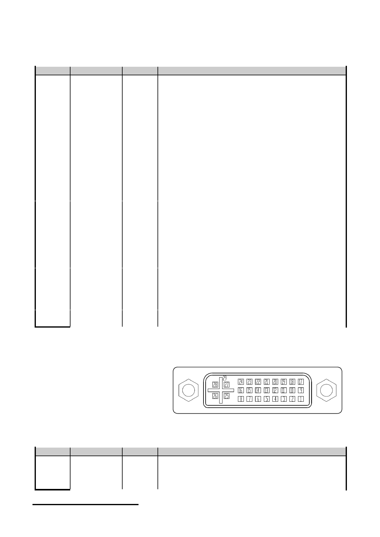
3.1 K1 Terminal (DVI FEMALE(24+5))
Pin No.
Pin Name
IO
Descriptions
1
RX2-
Input
LVDS receiver negative signal channel 2
2
RX2+
Input
LVDS receiver positive signal channel 2
3
GND
Power Ground
4
BL_PWM
Input
Backlight dimming control
5
NC
-
No connection
6
VDD
Power Positive power supply(5.0V)
7
VDD
Power Positive power supply(5.0V)
8
VDD
Power Positive power supply(5.0V)
9
RX1-
Input
LVDS receiver negative signal channel 1
10
RX1+
Input
LVDS receiver positive signal channel 1
11
GND
Power Ground
12
RX3-
Input
LVDS receiver negative signal channel 3
13
RX3+
Input
LVDS receiver positive signal channel 3
14
VDD
Power Positive power supply(5.0V)
15
GND
Power Ground
16
GND
Power Ground
17
RX0-
Input
LVDS receiver negative signal channel 0
18
RX0+
Input
LVDS receiver positive signal channel 0
19
GND
Power Ground
20
USB_DM
I/O
USB D- signal
21
USB_DP
I/O
USB D+ signal
22
GND
Power Ground
23
RXCLK+
Input
LVDS receiver positive signal clock
24
RXCLK-
Input
LVDS receiver negative signal clock
25
VDD
Power Positive power supply(5.0V)
26
VDD
Power Positive power supply(5.0V)
27
NC
-
No connection
28
NC
-
No connection
29
GND
Power Ground
--
SHELL
--
Case ground
Note:
The PWM duty cycle will adjust the brightness of the display accordingly through "automatic control "Display
brightness "function (refer to chapter 6.1)
3.2 K4 Terminal (Charging Indicator Interface (xh-2.54-4F or equivalent))
Pin No.
Pin Name
I/O
Descriptions
1
BLA
Power LED Positive
2
LED-YELLOW
Power LED-YELLOW Negative
3
LED-RED
Power LED-RED Negative
4
LED-GREEN
Power LED-GREEN Negative
NURL: www.topwaydisplay.com
Document Name: LMT070DICFWD-AKE(EN)
Page: 4 of 12

TOPWAY
LCD Module User Manual
LMT070DICFWD-AKE
3.3 K5 Terminal (Power Interface of Audio Drive Board( 3.81 terminal))
Pin No.
Pin Name
I/O
Descriptions
1
12V
Power
Power Supply of Audio Drive Board,12V
2
GND
Power
Power Supply of Audio Drive Board,GND
3.4 The signal interface of the audio drive board is a 3.5mm headphone jack, with left
channel input
4. Absolute Maximum Ratings
Items
Symbol
Min.
Max.
Unit
Condition
Power Supply voltage
VDD
-0.3
5.5
V
Operating Temperature
T OP
-20
70
C
No Condensation
Storage Temperature
T ST
-30
80
C
No Condensation
Relative humidity
HR
5%
95%
No Condensation
Note :
*1. This rating applies to all parts of the module. And should not be exceeded.
*2. The operating temperature only guarantees operation of the circuit. The contrast, response speed,
and the other specification related to electro-optical display quality is determined at the room temperature, T OP =25 ℃
*3. Any Stresses exceeding the Absolute Maximum Ratings may cause substantial damage to the device. Functional
operation of this device at other conditions beyond those listed in the specification is not implied and prolonged
exposure to extreme conditions may affect device reliability.
5. Electrical Characteristics
5.1 DC Characteristics
VDD=5.0V, GND=0V,T op =25 C
Items
Symbol
MIN.
TYP.
MAX.
Unit Note
Supply Voltage
VDD
4.7
5.0
5.3
V
VDD Power Consumption
I dd
--
0.5
--
A
*1
Backlight Life
50000
Hrs
Note *1: Backlight brightness is 100%.
5.1 DC Characteristics (LVDS)
VDD=5.0V, GND=0V, T op =25 C
Items
Symbol
MIN.
TYP.
MAX.
Unit Note
Differential Input High
-
100
mV
Threshold
V TH
-
Differential Input Low
-100
Threshold
V TL
-
-
mV
Input Current
I IN
± 10
uA
Differential Input common
Mode voltage
V CMLVDS
1.65
-
2.1
V
LVDS DC Characteristics
NURL: www.topwaydisplay.com
Document Name: LMT070DICFWD-AKE(EN)
Page: 5 of 12
TOPWAY
LCD Module User Manual
LMT070DICFWD-AKE
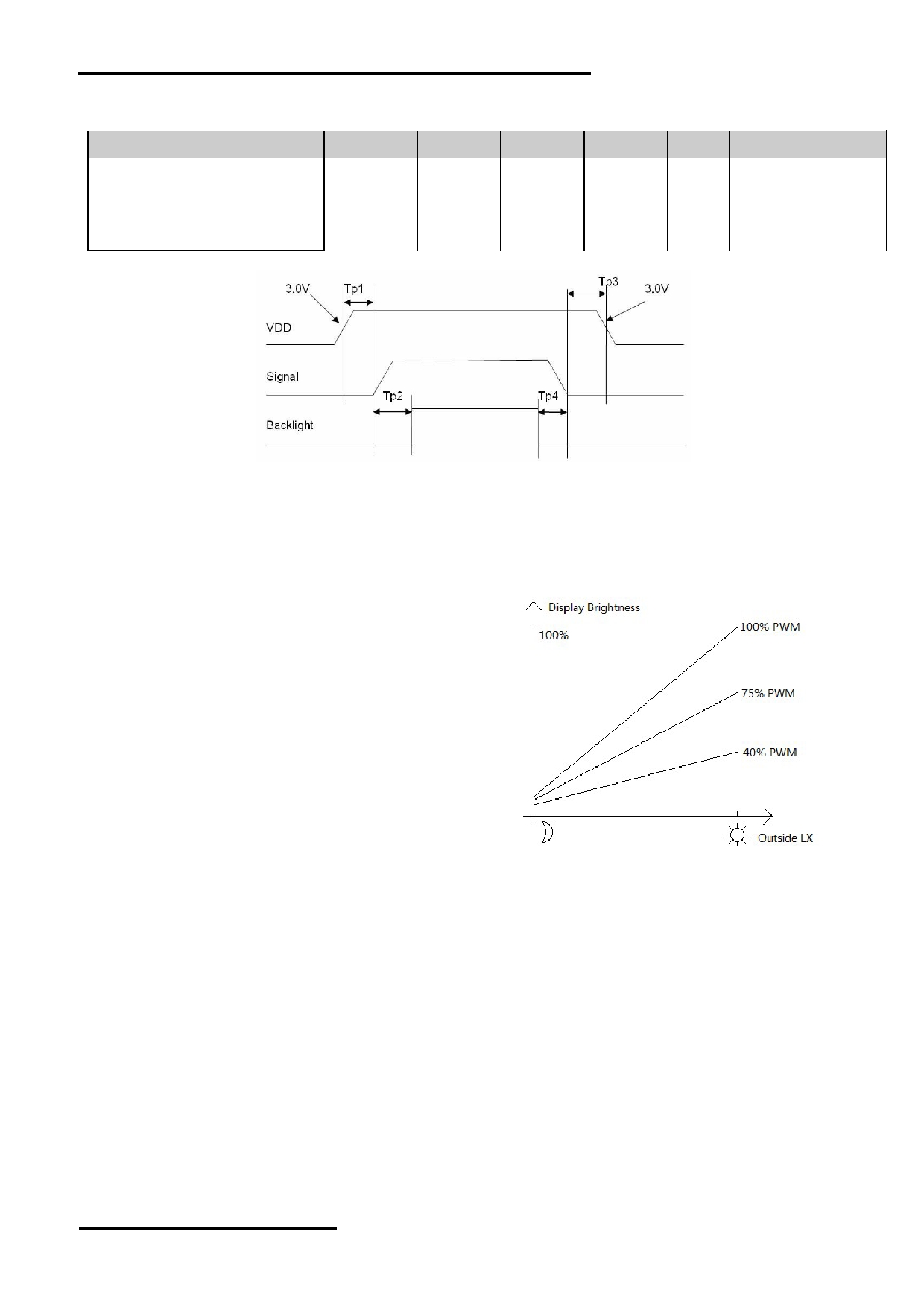
5.2 POWER ON/OFF SEQUENCE
Parameter
Symbol
MIN.
TYP.
MAX.
Unit Note
VDD 3.0V to signal starting
Tp1
0
-
50
ms
Signal staring to backlight on
Tp2
150
-
-
ms
Signal off to VDD 3.0V
Tp3
0
-
50
ms
Backlight off to signal off
Tp4
150
-
-
ms
Interface Power On/Off Sequence
6. Function introduction
6.1 Automatic Control of Display Brightness
The module is equipped with a photosensitive circuit
which can automatically control the brightness.
When the ambient lighting becomes low, the brightness
decreases (e.g. at night);
Automatic adjustment of light brightness based on PWM
adjustment.
NURL: www.topwaydisplay.com
Document Name: LMT070DICFWD-AKE(EN)
Page: 6 of 12
TOPWAY
LCD Module User Manual
LMT070DICFWD-AKE
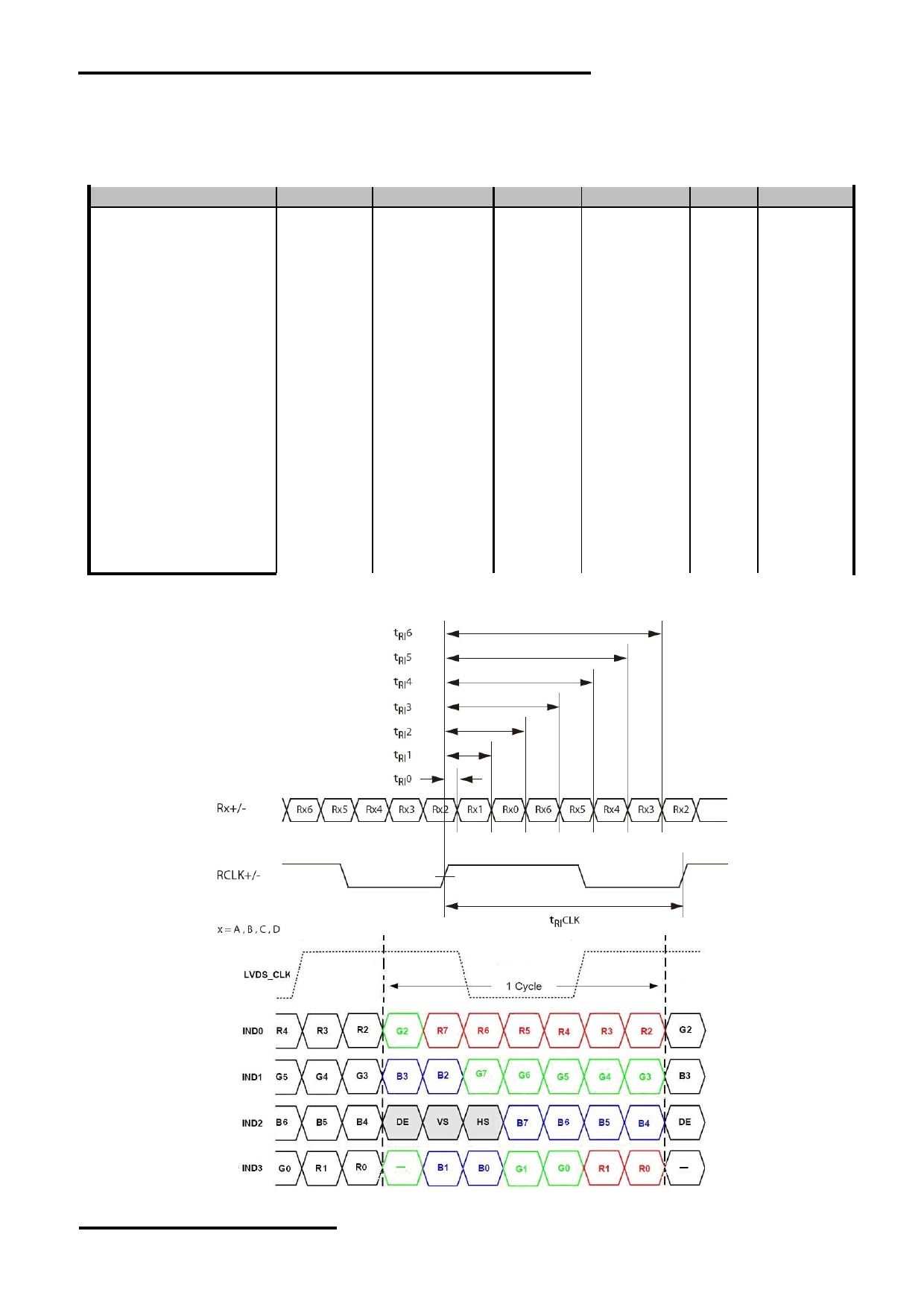
7. AC Characteristics
7.1
AC Characteristics(LVDS)
VDD=5.0V, GND=0V, T op =25 C
Item
Symbol
MIN.
TYP.
MAX.
Unit Condition
Input CLK period
t RI CLK
8.9
-
50
ns
Input Data Position 0
t RI 0
-0.3
-
+0.3
ns
( tRICLK = 8.9ns )
Input Data Position 1
t RI 1
t RI CLK/7-0.3
t RI CLK/7
t RI CLK/7+0.3
ns
(tRICLK = 8.9ns )
Input Data Position 2
t RI 2
2t RI CLK/7-0.3
2t RI CLK/7
2t RI CLK/7+0.3
ns
(tRICLK = 8.9ns )
Input Data Position 3
t RI 3
3t RI CLK/7-0.3
3t RI CLK/7
3t RI CLK/7+0.3
ns
(tRICLK = 8.9ns )
Input Data Position 4
t RI 4
4t RI CLK/7-0.3
4t RI CLK/7
4t RI CLK/7+0.3
ns
(tRICLK = 8.9ns )
Input Data Position 5
t RI 5
5t RI CLK/7-0.3
5t RI CLK/7
5t RI CLK/7+0.3
ns
(tRICLK = 8.9ns )
Input Data Position 6
t RI 6
6t RI CLK/7-0.3
6t RI CLK/7
6t RI CLK/7+0.3
ns
(tRICLK = 8.9ns )
Input Clock and Data timing Diagram:
NURL: www.topwaydisplay.com
Document Name: LMT070DICFWD-AKE(EN)
Page: 7 of 12
TOPWAY
LCD Module User Manual
LMT070DICFWD-AKE
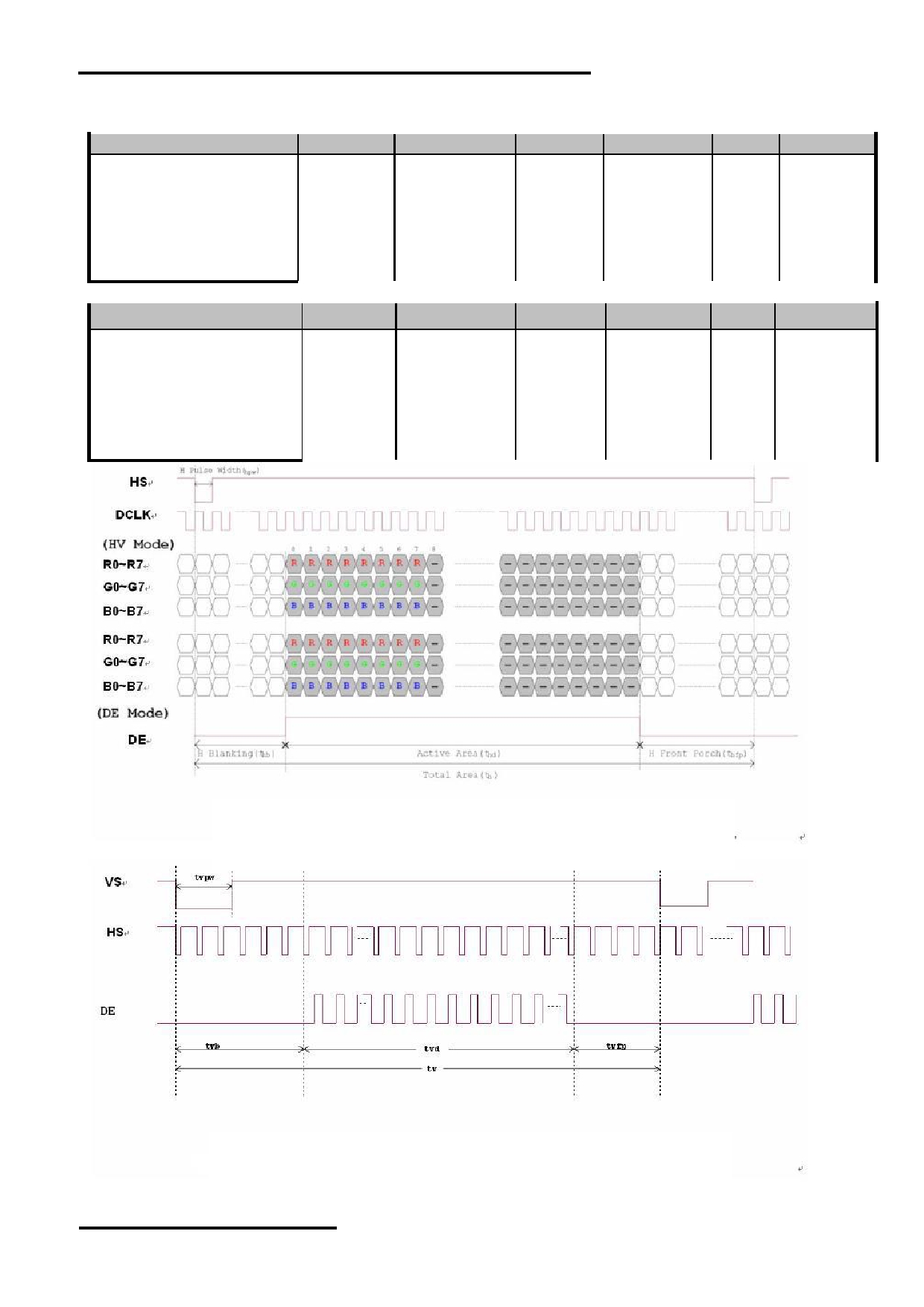
7.2
AC Characteristics(TFT)
Item
Symbol
MIN.
TYP.
MAX.
Unit Remark
Horizontal Display Area
thd
-
800
-
DCLK
DCLK Frequency
fclk
26.4
33.3
46.8
MHz
One Horizontal Line
th
862
1056
1200
DCLK
HS pulse width
thpw
1
-
40
DCLK
HS Blanking
thb
46
46
46
DCLK
HS Front Porch
thfp
16
210
354
DCLK
Item
Symbol
MIN.
TYP.
MAX.
Unit
Remark
Vertical Display Area
tvd
-
480
-
TH
VS period time
tv
510
525
650
TH
VS pulse width
tvpw
1
-
20
TH
VS Blanking
tvb
23
23
23
TH
VS Front Porch
tvfp
7
22
147
TH
Horizontal input timing diagram
Vertical input timing diagram
NURL: www.topwaydisplay.com
Document Name: LMT070DICFWD-AKE(EN)
Page: 8 of 12
TOPWAY
LCD Module User Manual
LMT070DICFWD-AKE
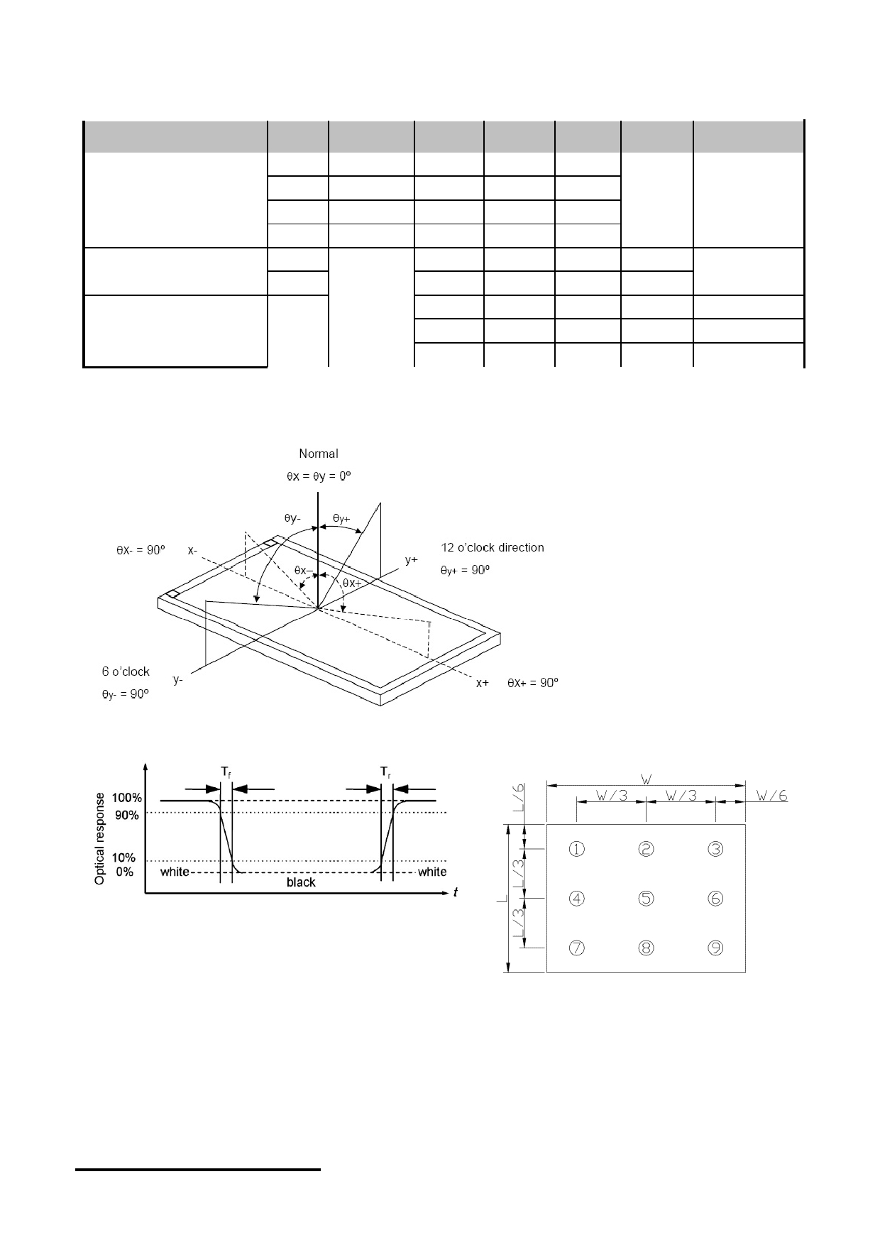
8. Optical Characteristics
Item
Symbo
l
Condition MIN.
TYP.
MAX.
Unit
Note
θ L
9 o’clock
60
70
-
Viewing angle
θ R
3 o’clock
60
70
-
(CR ≥ 10)
度数
*2
θ T
12 o’clock
50
60
-
θ B
6 o’clock
60
70
-
T f
-
10
20
msec
Response Time
*3
T r
-
15
30
msec
Normal
Contrast ratio
CR
θ=0 o
400
500
-
-
*1
Luminance
L
-
900
-
cd/m 2
*4
Luminance uniformity
Y U
70
75
-
%
*4
Note:
*1. Definition of Contrast Ratio
The contrast ratio could be calculate by the following expression:
Contrast Ratio (CR) = Luminanc with all pixels white / Luminance with all pixels black
2 Definition of Viewing Angle
* 3 Definition of response time
*4 Definition of Luminance Uniformity
Luminance uniformity (Lu)=
Min. Luminance form pt1~pt9 / Max Luminance form Pt1~pt9
NURL: www.topwaydisplay.com
Document Name: LMT070DICFWD-AKE(EN)
Page: 9 of 12

TOPWAY
LCD Module User Manual
LMT070DICFWD-AKE
9. LCD Module Design and Handling Precaution
- Please ensure V0, VCOM is adjustable, to enable LCD module get the best contrast ratio under different temperatures, view angles and -
positions.
- Normally display quality should be judged under the best contrast ratio within viewable area. Unexpected display pattern may com out under
abnormal contrast ratio.
- Never operate the LCD module exceed the absolute maximum ratings.
- Never apply signal to the LCD module without power supply.
- Keep signal line as short as possible to reduce external noise interference.
- IC chip (e.g. TAB or COG) is sensitive to light. Strong light might cause malfunction. Light sealing structure casing is recommended.
- Make sure there is enough space (with cushion) between case and LCD panel, to prevent external force passed on to the panel; otherwise that
may cause damage to the LCD and degrade its display result.
- Avoid showing a display pattern on screen for a long time (continuous ON segment).
- LCD module reliability may be reduced by temperature shock.
- When storing and operating LCD module, avoids exposure to direct sunlight, high humidity, high or low temperature. They may damage or
degrade the LCD module.
- Never leave LCD module in extreme condition (max./min storage/operate temperature) for more than 48hr.
- Recommend LCD module storage conditions is 0 C~40 C <80%RH.
- LCD module should be stored in the room without acid, alkali and harmful gas.
- Avoid dropping & violent shocking during transportation, and no excessive pressure press, moisture and sunlight.
- LCD module can be easily damaged by static electricity. Please maintain an optimum anti-static working environment to protect the LCD
module. (eg. ground the soldering irons properly)
- Be sure to ground the body when handling LCD module.
- Only hold LCD module by its sides. Never hold LCD module by applying force on the heat seal or TAB.
- When soldering, control the temperature and duration avoid damaging the backlight guide or diffuser which might degrade the display result
such as uneven display.
- Never let LCD module contact with corrosive liquids, which might cause damage to the backlight guide or the electric circuit of LCD module.
- Only clean LCD with a soft dry cloth, Isopropyl Alcohol or Ethyl Alcohol. Other solvents (e.g. water) may damage the LCD.
- Never add force to components of LCD module. It may cause invisible damage or degrade the module's reliability.
- When mounting LCD module, please make sure it is free from twisting, warping and bending.
- Do not add excessive force on surface of LCD, which may cause the display color change abnormally.
- LCD panel is made with glass. Any mechanical shock (e.g. dropping from high place) will damage the LCD module.
- Protective film is attached on LCD screen. Be careful when peeling off this protective film, since static electricity may be generated.
-
- Polarizer on LCD gets scratched easily. If possible, do not remove LCD protective film until the last step of installation.
- When peeling off protective film from LCD, static charge may cause abnormal display pattern. The symptom is normal, and it will turn back to
normal in a short while.
- LCD panel has sharp edges, please handle with care.
- Never attempt to disassemble or rework LCD module.
- If display panel is damaged and liquid crystal substance leaks out, be sure not to get any in your mouth, if the substance comes into contact
with your skin or clothes promptly wash it off using soap and water.
NURL: www.topwaydisplay.com
Document Name: LMT070DICFWD-AKE(EN)
Page: 10 of 12
TOPWAY
LCD Module User Manual
LMT070DICFWD-AKE
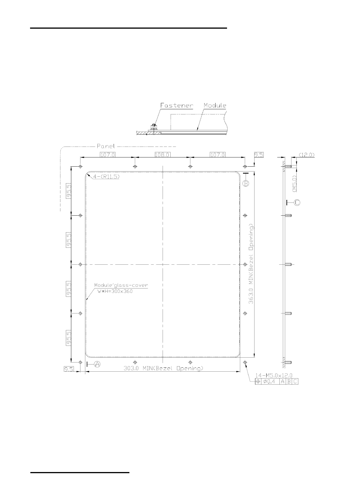
10. Product Mounting Precaution
- Use flange type panel for installation ( Figure 1 )
- It is recommended that the installation panel of the customer's equipment be designed as follows:
Panel window size: W * H ≥ 303 * 363mm
M5 screw column is used for the panel
- If the panel accuracy is difficult to guarantee, M4 screw column can be selected.
- See Figure 2 for specific installation panel size.
Figure 1
Figure 2
- The panel window shall have sufficient rigidity and good flatness to facilitate installation, sealing and waterproof.
- Adopt conventional tightening methods, that is, use flat washers, elastic washers and nuts to ensure normal installation and locking.
- Appropriate locking force shall be applied when tightening the nut to prevent from deformation of the module aluminum plate.
NURL: www.topwaydisplay.com
Document Name: LMT070DICFWD-AKE(EN)
Page: 11 of 12

TOPWAY
LCD Module User Manual
LMT070DICFWD-AKE
Warranty
This product has been manufactured to our company’s specifications as a part for use in your company’s general electronic
products. It is guaranteed to perform according to delivery specifications. For any other use apart from general electronic
equipment, we cannot take responsibility if the product is used in medical devices, nuclear power control equipment,
aerospace equipment, fire and security systems, or any other applications in which there is a direct risk to human life and
where extremely high levels of reliability are required. If the product is to be used in any of the above applications, we will
need to enter into a separate product liability agreement.
- We cannot accept responsibility for any defect, which may arise form additional manufacturing of the product (including
disassembly and reassembly), after product delivery.
- We cannot accept responsibility for any defect, which may arise after the application of strong external force to the
product.
- We cannot accept responsibility for any defect, which may arise due to the application of static electricity after the
product has passed our company’s acceptance inspection procedures.
- When the product is in CCFL models, CCFL service life and brightness will vary according to the performance of the
inverter used, leaks, etc. We cannot accept responsibility for product performance, reliability, or defect, which may arise.
- We cannot accept responsibility for intellectual property of a third part, which may arise through the application of our
product to our assembly with exception to those issues relating directly to the structure or method of manufacturing of
our product.
NURL: www.topwaydisplay.com
Document Name: LMT070DICFWD-AKE(EN)
Page: 12 of 12