LMT080ENEFWA
LCD Module User Manual
Prepared by:
Checked by:
Approved by:
LuoLin
Date: 2026-09-29
Date:
Date:
Rev. Descriptions
Edit
Release Date
0.1
Preliminary release
LuoLin
2026-09-29
URL: www.topwaydisplay.com
Document Name: LMT080ENEFWA-Manual-Rev0.1.DOC

TOPWAY
LCD Module User Manual
LMT080ENEFWA
-
CONTENTS
1. SUMMARY........................................................................................................................................................ 1
1.1 General Description ..................................................................................................................................................................................... 1
1.2 Features ........................................................................................................................................................................................................... 1
2. GENERAL SPECIFICATIONS .......................................................................................................................... 2
3. INPUT / OUTPUT TERMINALS..................................................................................................................... 3
3.1 CN1 Pin assignment (LCD Interface) ..................................................................................................................................................... 3
4. ABSOLUTE MAXIMUM RATINGS ............................................................................................................... 5
5. ELECTRICAL CHARACTERISTICS ................................................................................................................. 6
5.1 DC Characteristics for Panel Driving ...................................................................................................................................................... 6
5.2 DC Characteristics for Backlight Driving ............................................................................................................................................... 6
5.3 Recommended Power ON/OFF Sequence .......................................................................................................................................... 7
5.4 LCD Module Block Diagram ..................................................................................................................................................................... 8
6. TIMING CHARACTERISTICS ......................................................................................................................... 9
6.1 AC characteristics ......................................................................................................................................................................................... 9
6.2 Data Input Timing Parameter Setting ................................................................................................................................................. 10
7. OPTICAL CHARACTERISTICS ..................................................................................................................... 12
8. RELIABILITY TEST .......................................................................................................................................... 15
9. MECHANICAL DRAWING ........................................................................................................................... 16
10.
PRECAUTIONS FOR USE OF LCD MODULES ...................................................................................... 18
10.1
Handling Precautions........................................................................................................................................................................... 18
10.2
Storage precautions ............................................................................................................................................................................. 18
10.3
Transportation Precautions ............................................................................................................................................................... 18
10.4
Screen saver Precautions .................................................................................................................................................................... 18
10.5
Safety Precautions ................................................................................................................................................................................ 18
URL: www.topwaydisplay.com
Document Name: LMT080ENEFWA-Manual-Rev0.1.DOC

TOPWAY
LCD Module User Manual
LMT080ENEFWA
-
1.
Summary
1.1 General Description
This is a 8.0 inch a-Si TFT-LCD module with Normal-black technology. It is composed of a TFT-LCD panel,
a driver circuit, FPC, and a LED backlight unit.
1.2 Features
Amending Annex II of 2011/65/EU)
URL: www.topwaydisplay.com
Document Name: LMT080ENEFWA-Manual-Rev0.1.DOC
1
TOPWAY
LCD Module User Manual
LMT080ENEFWA
-
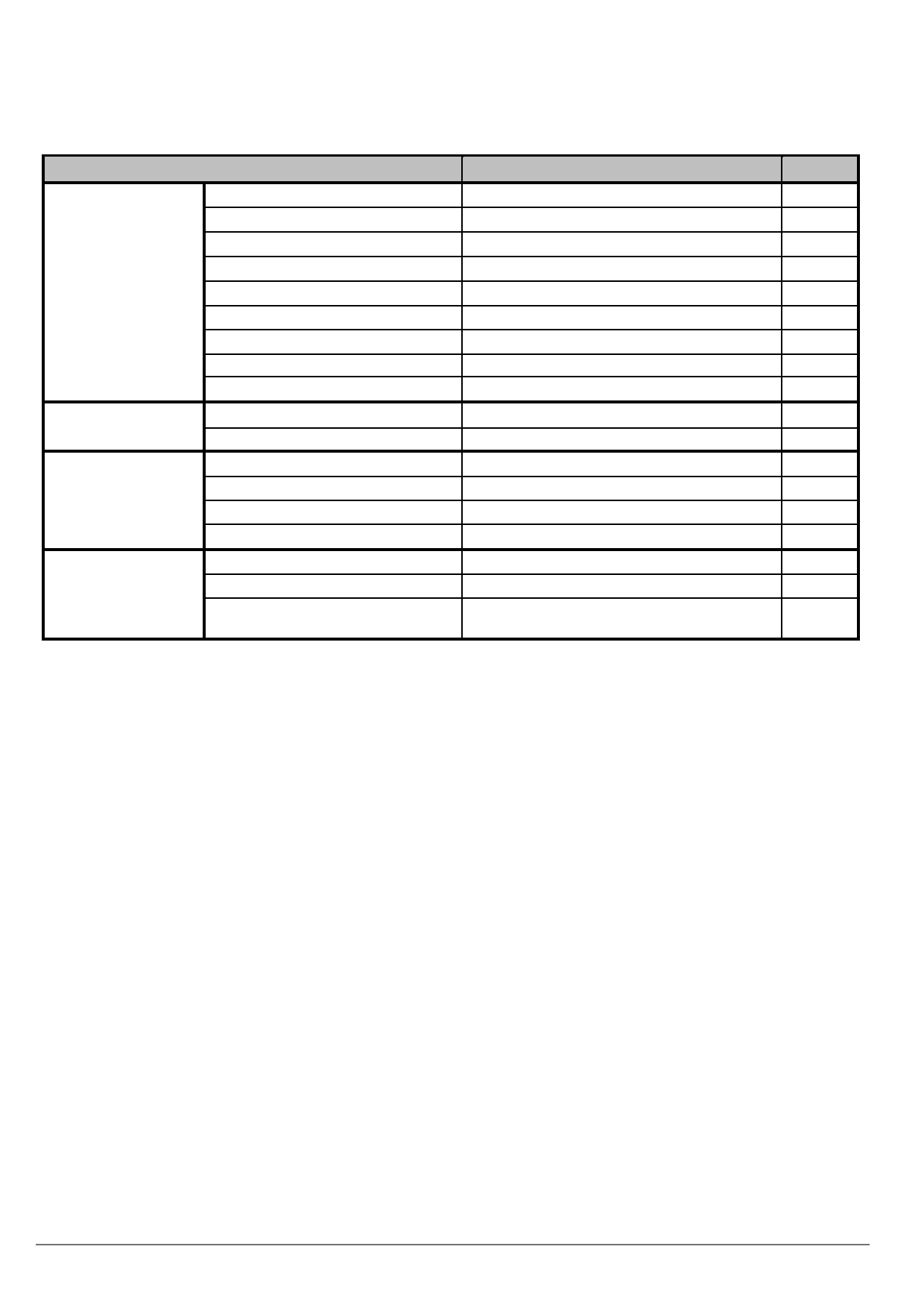
2.
General Specifications
Feature
Spec
Unit
Size
8.0 inches
Resolution
800(RGB) x 600
Pixel Pitch
0.2025(H) x 0.2025 (V)
mm
TFT Active Area
162.0 (W) x121.5 (H)
mm
Display Spec
Technology Type
a-Si
Pixel Configuration
R.G.B Vertical Stripe
Display Mode
SFT, Normally Black
Surface Treatment
Anti-Glare
Viewing Direction
All
Mechanical
LCM (W x H x D)
183.0×141.0×5.6
mm
Characteristics
Weight
210
g
2
Luminance
350
cd/m
Optical
Contrast Ratio
1000:1
Characteristics
NTSC
50
%
Viewing Angle
89/89/89/89
degree
Interface
RGB 24 bits
Electrical
Color Depth
16.7 Million
color
Characteristics
Power Consumption
LCD: TBD
Backlight: 1620
mW
Table 2.1 General TFT Specifications
URL: www.topwaydisplay.com
Document Name: LMT080ENEFWA-Manual-Rev0.1.DOC
2
TOPWAY
LCD Module User Manual
LMT080ENEFWA
-
3.
Input / Output Terminals
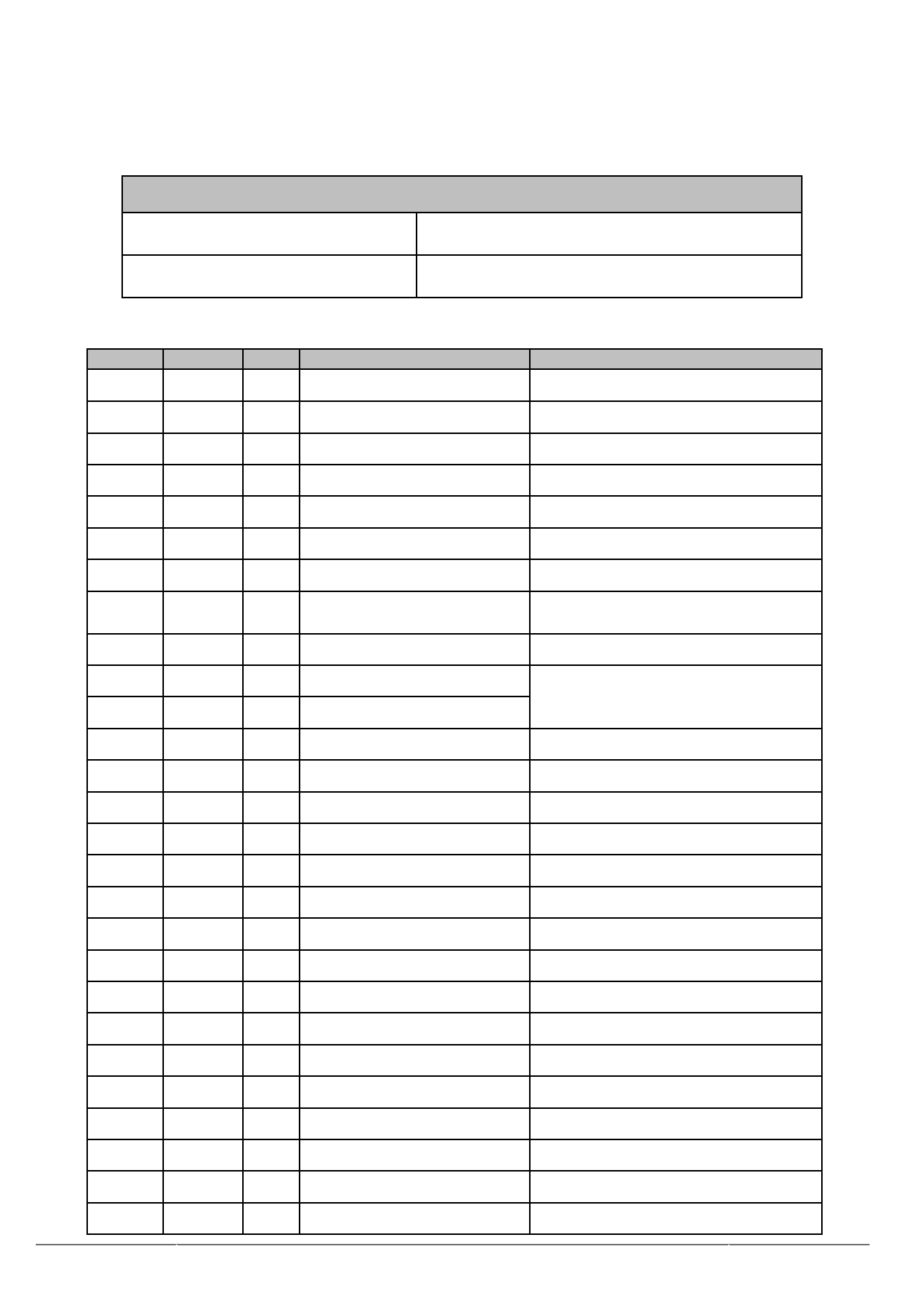
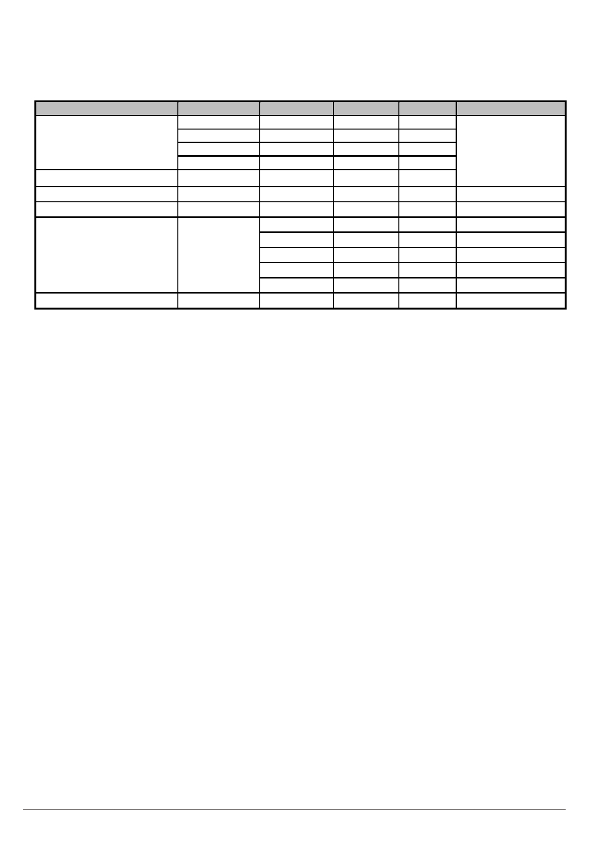
3.1 CN1 Pin assignment (LCD Interface)
Connector Information
Connector
0.5pitch 50pin FPC
Matching connector
FH52-50S-0.5SH or compatible
Table 3.1.1 Connector information
Pin No.
Symbol
I/O
function
Remarks
1
LED+
P
LED Anode
2
LED+
P
LED Anode
3
LED-
P
LED Cathode
4
LED-
P
LED Cathode
5
GND
P
Power ground
6
NC
N
No connection
7
VCC
P
Power supply 3.3V
8
MODE
I
DE/SYNC mode select
MODE=1,DE mode ;
MODE=0, HSD/VSD mode.
9
DE
I
Data input enable
10
VS
I
Vertical sync input
Fix to GND when not used.
11
HS
I
Horizontal sync Input
12
B7
I
Blue data(MSB)
13
B6
I
Blue data
14
B5
I
Blue data
15
B4
I
Blue data
16
B3
I
Blue data
17
B2
I
Blue data
18
B1
I
Blue data
19
B0
I
Blue data(LSB)
20
G7
I
Green data(MSB)
21
G6
I
Green data
22
G5
I
Green data
23
G4
I
Green data
24
G3
I
Green data
25
G2
I
Green data
26
G1
I
Green data
27
G0
I
Green data(LSB)
URL: www.topwaydisplay.com
Document Name: LMT080ENEFWA-Manual-Rev0.1.DOC
3
TOPWAY
LCD Module User Manual
LMT080ENEFWA
-
28
R7
I
RED data(MSB)
29
R6
I
RED data
30
R5
I
RED data
31
R4
I
RED data
32
R3
I
RED data
33
R2
I
RED data
34
R1
I
RED data
35
R0
I
RED data(LSB)
36
GND
P
Power ground
37
DCLK
I
Clock for input data
Latch data at falling edge.
38
GND
P
Power ground
39
NC
N
No connection
40
NC
N
No connection
41
VGH
P
No connection
42
VGL
P
No connection
43
AVDD
P
No connection
44
RESET
I
Global reset pin
Controlled by MCU or connected
with RC delay.
45
NC
N
No connection
46
NC
N
No connection
47
NC
N
No connection
48
GND
P
Power ground
49
NC
N
No connection
50
NC
N
No connection
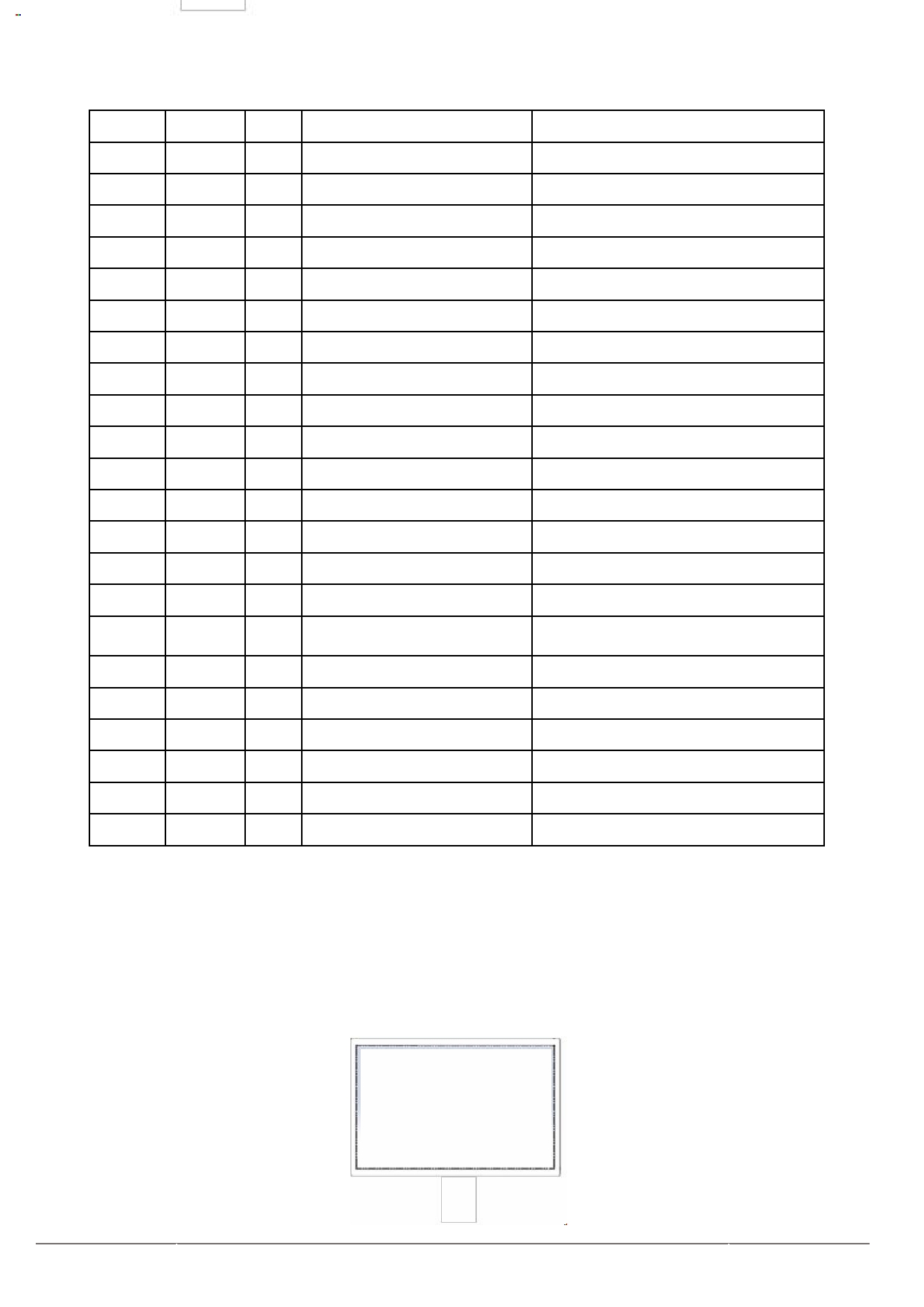
Table 3.1.2 Pin Assignment for LCD Interface
Note1: I/O definition: I---Input, O---Output, P---Power/Ground, N---No connection
Note2: All of the GND pins should be connected to the system ground.
Note3: This LCD module supports SYNC & SYNC-DE & DE mode, the pin setting is different from each other.
Please refer to the descriptions.
Note4 : Display direction is shown as the figure below:
TOPWAY
-
URL: www.topwaydisplay.com
Document Name: LMT080ENEFWA-Manual-Rev0.1.DOC
4
TOPWAY
-
LCD Module User Manual
LMT080ENEFWA
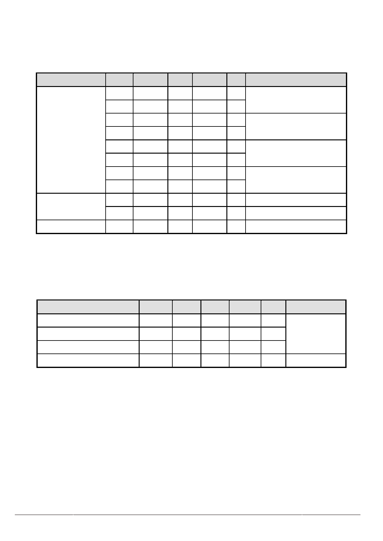
4. Absolute Maximum Ratings
Item
Symbol
MIN
MAX
Unit
Remark
VCC
-0.5
5.0
V
AVDD
-0.5
12
V
Power Voltage
VGH
-0.3
+20
V
Note1
VGL
VGH-32
+0.3
V
Input voltage
V IN
-0.5
5.0
V
Operating Temperature
Top
-20
70
℃
Storage Temperature
Tst
-30
80
℃
--
≤95
%
Ta≤40 ℃
--
≤85
%
40 ℃< Ta≤50 ℃
Relative Humidity
Note2
RH
--
≤55
%
50 ℃< Ta≤60 ℃
--
≤36
%
60 ℃< Ta≤70 ℃
--
≤24
%
70 ℃< Ta≤80 ℃
Absolute Humidity
AH
--
≤70
g/m³
Ta > 70 ℃
Table 4.1 Absolute Maximum Ratings
Note1: Input voltage include all input data.
Note2: Ta means the ambient temperature. It is necessary to limit the relative humidity to the specified
temperature range. Condensation on the module is not allowed.
Note3: The absolute maximum rating values of this product are not allowed to be exceeded at any times. A
module should be used with any of the absolute maximum ratings exceeded, the characteristics of the
module may not be recovered, or in an extreme condition, the module may be permanently destroyed.
URL: www.topwaydisplay.com
Document Name: LMT080ENEFWA-Manual-Rev0.1.DOC
5
TOPWAY
LCD Module User Manual
LMT080ENEFWA
-
5.
Electrical Characteristics
5.1 DC Characteristics for Panel Driving
Item
Symbol
Min
Typ
Max
Unit
Remark
VCC
3.0
3.3
3.6
V
Digital Supply Voltage
I VCC
--
TBD
--
mA
AVDD
--
10.4
--
V
Analog Supply Voltage
Power
I AVDD
--
TBD
--
mA
Voltage&Current
VGH
--
19
--
V
Gate On Voltage
I VGH
--
TBD
--
mA
VGL
--
-7
--
V
Gate Off Voltage
I VGL
--
TBD
--
mA
V IH
0.7VCC
--
VCC
Input voltage
V IL
0
--
0.3VCC
Power Consumption
P
--
TBD
--
mW All white pattern
Table 5.1.1 Operating Voltages
Note1: Input voltage includes R0~R7, G0~G7, B0~B7, DCLK, HS, VS, MODE, DE, L/R, U/D,
RESET.
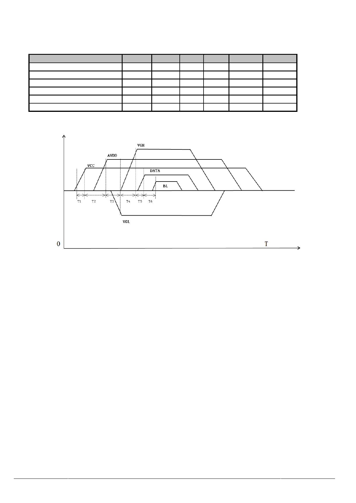
5.2 DC Characteristics for Backlight Driving
Item
Symbol
Min
Typ
Max
Unit
Remark
Forward Current
I F
-
180
225
mA
27 LEDs
Forward Voltage
V F
8.1
9.0
9.6
V
(3 LED Serial, 9
LED Parallel)
Backlight Power Consumption
W BL
-
1.62
2.18
W
Operating Life Time
-
20000
-
-
Hrs
I LED =20mA
Table 5.2.1 LED Backlight Characteristics
Note1: I is defined for total channel.
F
Note2: Optical performance should be evaluated at Ta=25 ℃ only.
Note3: If LED is driven by high current, high ambient temperature & humidity condition,The life time of LED will
be reduced.
Note4: Operating life means brightness goes down to 50% of initial brightness. Typical operating life time is
estimated data.
URL: www.topwaydisplay.com
Document Name: LMT080ENEFWA-Manual-Rev0.1.DOC
6
TOPWAY
LCD Module User Manual
LMT080ENEFWA
-
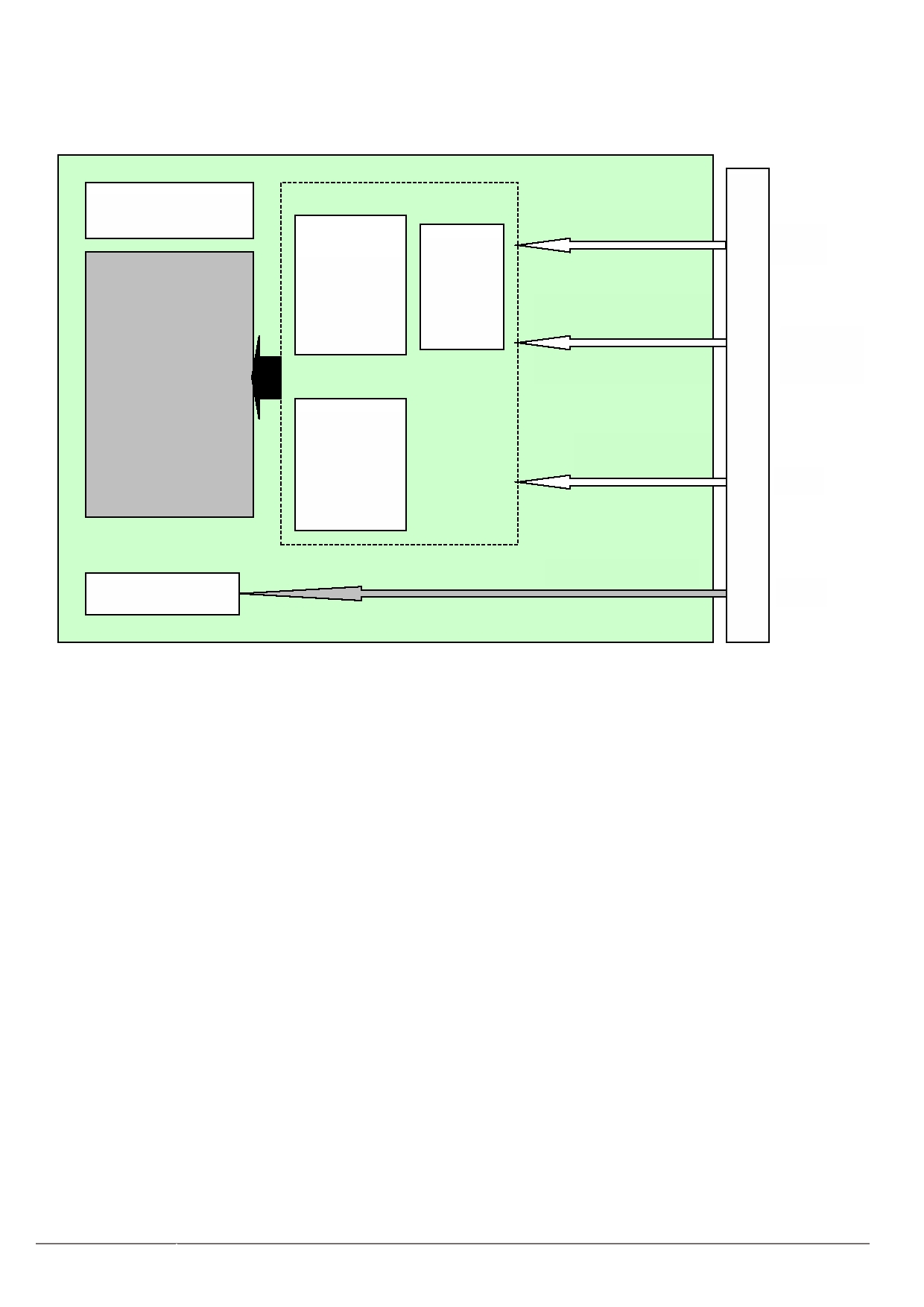
5.3 Recommended Power ON/OFF Sequence
Item
Symbol
Min
Typ
Max
Unit
Remark
VCC 3.3V rising time
T1
0
-
5
ms
VCC to AVDD on time
T2
-
TBD
-
ms
AVDD to VGL on time
T3
-
TBD
-
ms
VGL to VGH on time
T4
-
TBD
-
ms
VGH to DATA on time
T5
-
TBD
-
ms
DATA to BL on time
T6
-
TBD
-
ms
Figure 5.3.1 Power on/off sequence
Figure 5.3.2 Power on/off sequence
Note1: The low level of these signals and analog powers are GND level.
Note2: All of the power and signals should be kept at GND level before power on. If there are residual voltages
on them, the LCD might not work properly.
Note3: The power on/off sequence is the first version. It will be updated when the design is fixed.
Note4: BL is the voltage applied to backlight. Keep it turned off until the display has stabilized.
URL: www.topwaydisplay.com
Document Name: LMT080ENEFWA-Manual-Rev0.1.DOC
7
TOPWAY
-
LCD Module User Manual
LMT080ENEFWA
5.4 LCD Module Block Diagram
LCD Panel
R[7:0],G[7:0],B[7:0]
Data
VCOM
bus
Source + Gate
&
Driver
TCON
VS,HS,DE,DCLK,
7 inch
MODE,RESET,
800(RGB)*480
Control
signal
input
Grayscale
Manipulation
VCC,GND,VGH,
Voltage
VGL,AVDD
Power
LED+,LED-
BLU
BLU
Figure 5.4.1 LCD Module Block Diagram
URL: www.topwaydisplay.com
Document Name: LMT080ENEFWA-Manual-Rev0.1.DOC
8
TOPWAY
LCD Module User Manual
LMT080ENEFWA
-
6.
Timing Characteristics
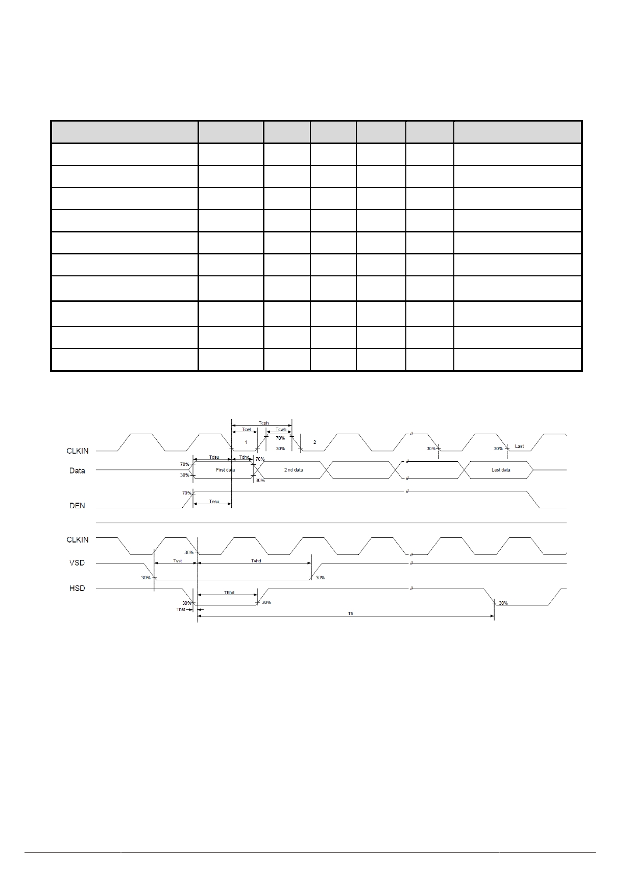
6.1 AC characteristics
Parameter
Symbol
Min
Typ
Max
Unit
Conditions
DCLK Cycle Time
Tcph
14
-
-
ns
DCLK Pulse Duty
Tcwh
40
50
60
%
VSD Setup Time
Tvst
5
-
-
ns
VSD Hold Time
Tvhd
5
-
-
ns
HSD Setup Time
Thst
5
-
-
ns
HSD Hold Time
Thhd
5
-
-
ns
D0[7:0],D1[7:0],D2[7:0]
Data Setup Time
Tdsu
5
-
-
ns
to DCLK
D0[7:0],D1[7:0],D2[7:0]
Data Hold Time
Tdhd
5
-
-
ns
to DCLK
DE Setup Time
Tesu
5
-
-
ns
DE Hold Time
Tehd
5
-
-
ns
Table 6.1.1 Input Setup Timing Parameters Requirement
Figure 6.1.1 Clock and Data Input Timing Diagram
URL: www.topwaydisplay.com
Document Name: LMT080ENEFWA-Manual-Rev0.1.DOC
9
TOPWAY
LCD Module User Manual
LMT080ENEFWA
-
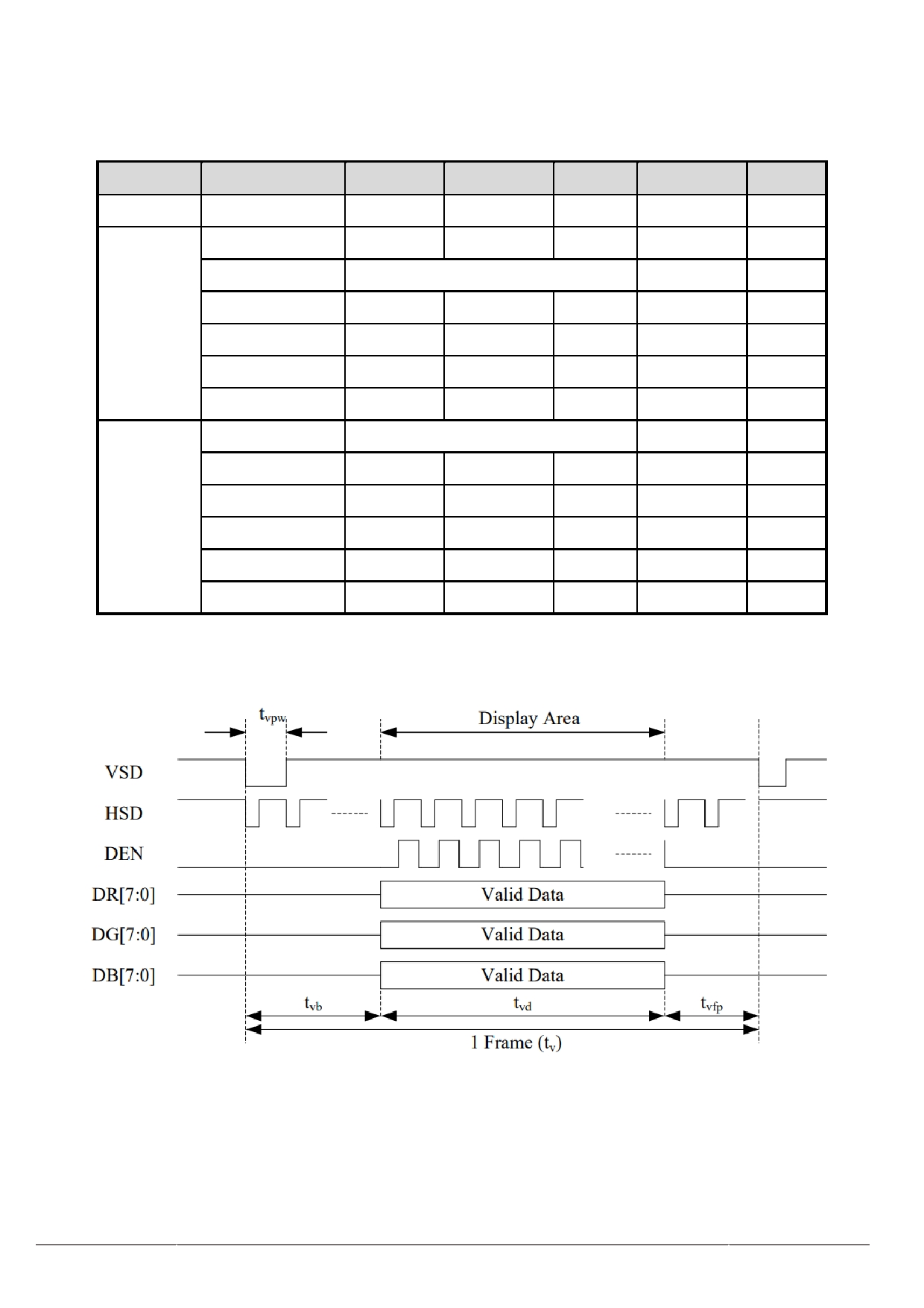
6.2 Data Input Timing Parameter Setting
TCON (Embedded In Source IC) Input Timing (DCLK, HSD, VSD, DE)
Parameter
Symbol
Min
Typ
Max
Unit
Remark
DCLK
F clk
32.6
39.6
62.4
MHZ
Th
890
1000
1300
DCLK
Thd
800
DCLK
Blanking
90
200
500
DCLK
HSD
Pulse width
1
24
HBP-1
DCLK
Thbp
60
88
250
DCLK
Thfp
30
112
250
DCLK
Tvd
600
Th
Tv
610
660
800
Th
Blanking
20
60
200
Th
VSD
Pulse width
1
2
VBP-1
Th
Tvbp
8
39
100
Th
Tvfp
2
21
100
Th
Table 6.2.1 Data Input Timing Parameters
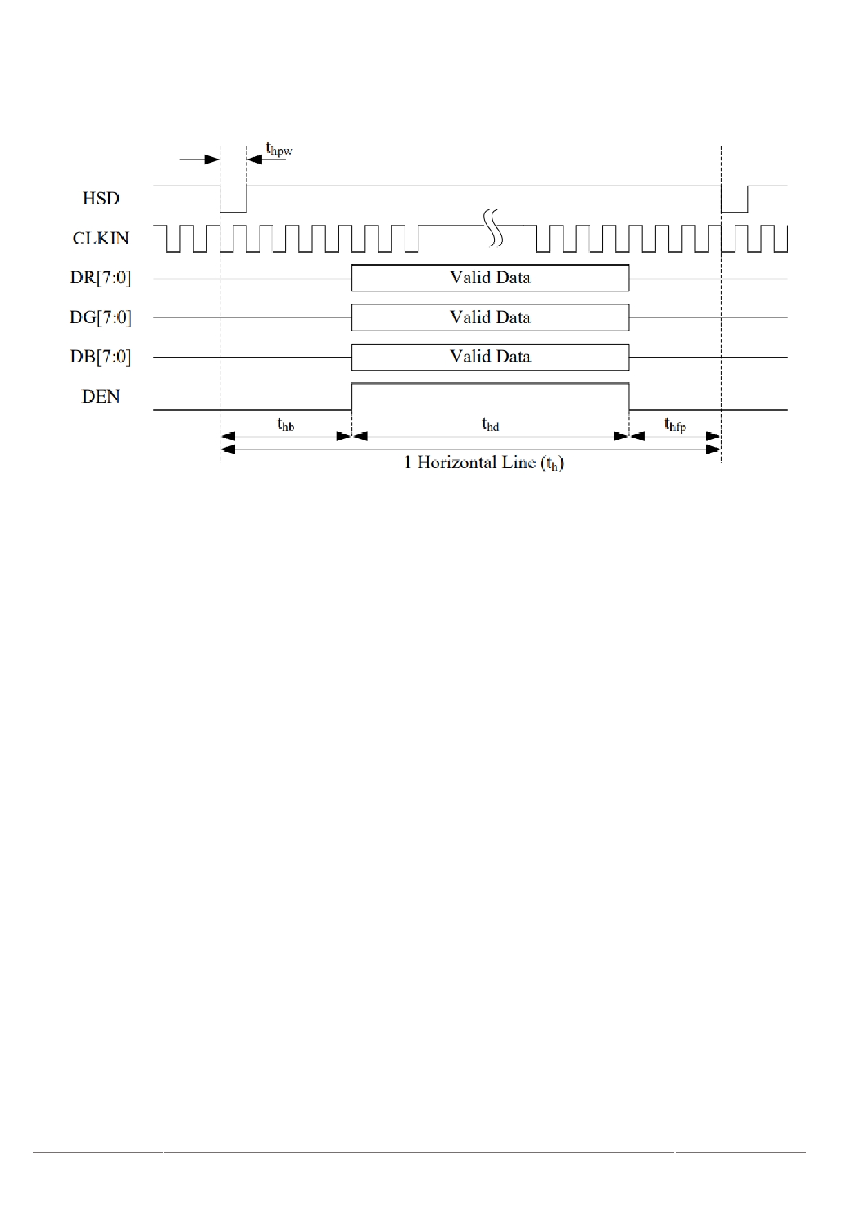
Vertical input timing Diagram:
URL: www.topwaydisplay.com
Document Name: LMT080ENEFWA-Manual-Rev0.1.DOC
10
TOPWAY
-
LCD Module User Manual
LMT080ENEFWA
Horizontal input timing Diagram:
Figure 6.2.1 Input timing Diagram
URL: www.topwaydisplay.com
Document Name: LMT080ENEFWA-Manual-Rev0.1.DOC
11
TOPWAY
-
LCD Module User Manual
LMT080ENEFWA
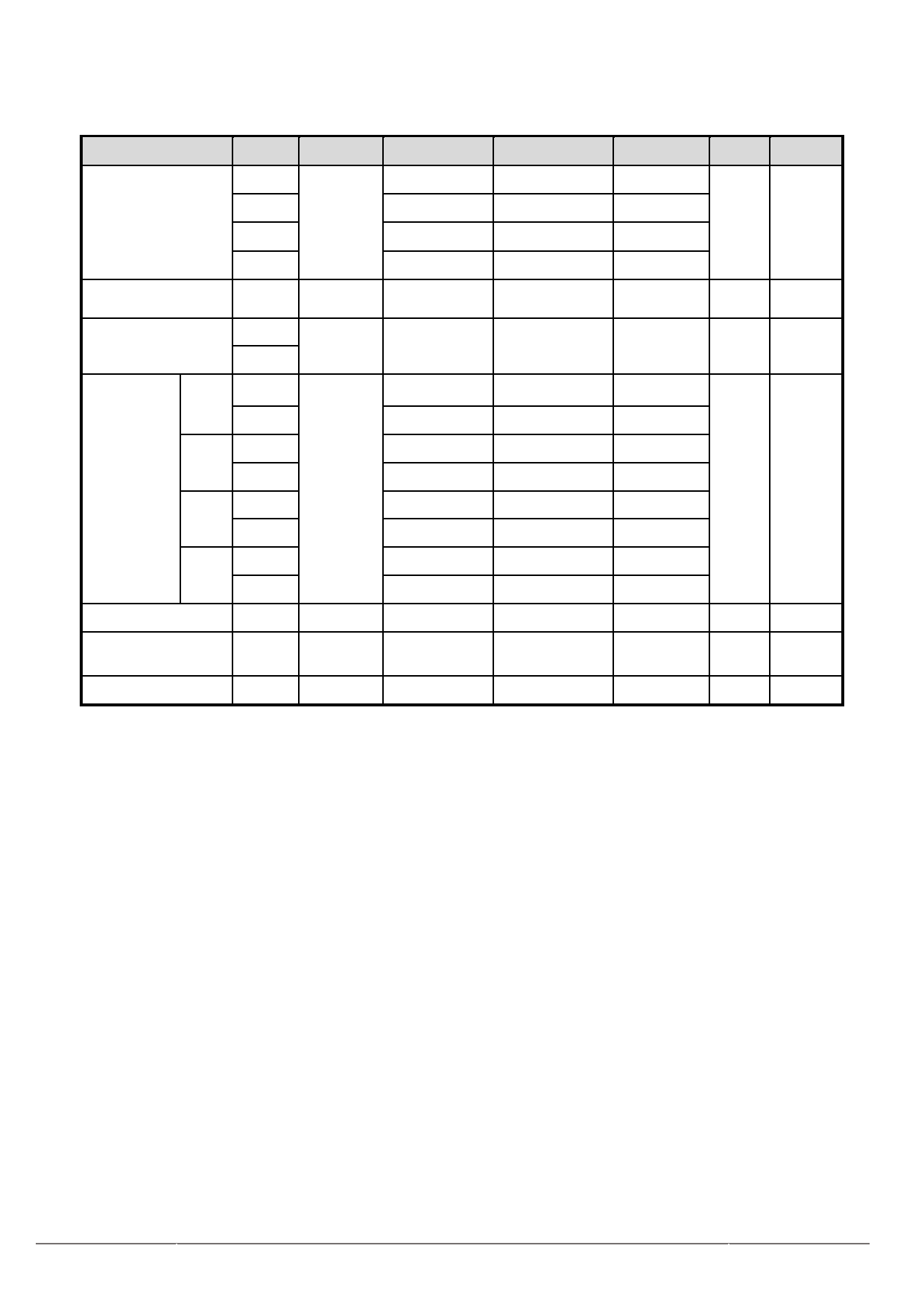
7. Optical Characteristics
Item
Symbol Condition
Min
Typ
Max
Unit Remark
θ T
80
89
-
θ B
80
89
-
View Angles
CR ≧ 10
Degree Note 2,3
θ L
80
89
-
θ R
80
89
-
Contrast Ratio
CR
θ = 0 °
800
1000
-
Note3
T ON
Response Time
25 ℃
-
25
35
ms
Note4
T OFF
x
0.249
0.299
0.349
White
y
0.275
0.325
0.375
x
0.519
0.569
0.619
Red
y
0.290
0.340
0.390
Note1
Chromaticity
Backlight
x
is on
0.288
0.338
0.388
Note5
Green
y
0.543
0.593
0.643
x
0.099
0.149
0.199
Blue
y
0.038
0.088
0.138
Uniformity
U
70
75
-
%
Note6
NTSC
45
50
-
%
Note 5
cd/m Note7
2
Luminance
L
300
350
-
Table 7.1 Optical Parameters
Test Conditions:
1. I F = 20 mA, and the ambient temperature is 25 ℃ .
2. The test systems refer to Note1 and Note2.
URL: www.topwaydisplay.com
Document Name: LMT080ENEFWA-Manual-Rev0.1.DOC
12
TOPWAY
LCD Module User Manual
LMT080ENEFWA
-
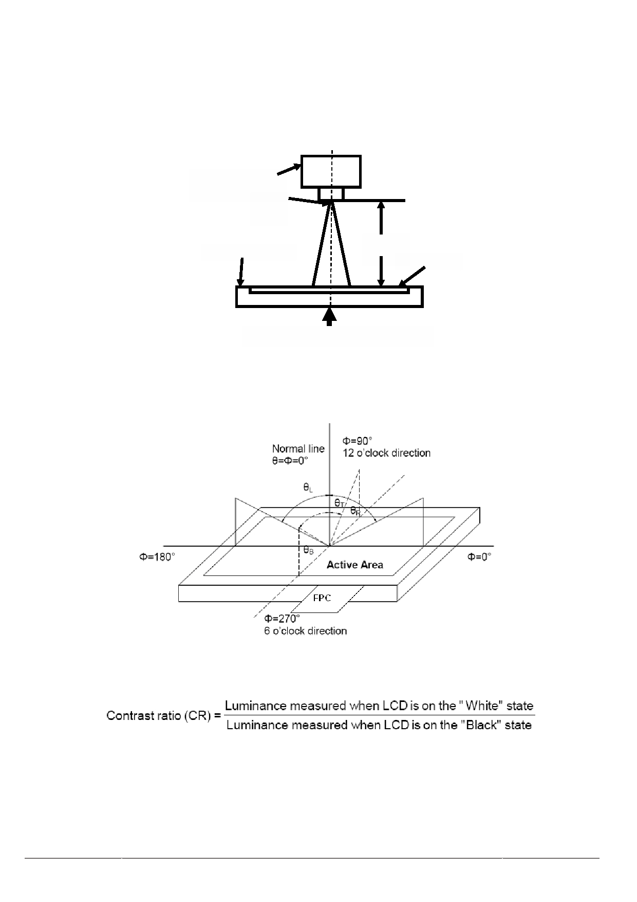
Note1: Definition of optical measurement system.
The optical characteristics should be measured in dark room. After 5 Minutes operation, the optical
characteristics are measured at the center point of the LCD screen.
Photo detector
Field
500mm
TFT-LCD Module
LCD Panel
The center of the screen
Fig1. Measurement Set Up
Note2: Definition of viewing angle range and measurement system. Viewing angle is measured at the center
point of the LCD 。
Fig2. Measurement viewing angle
Note3: Definition of contrast ratio
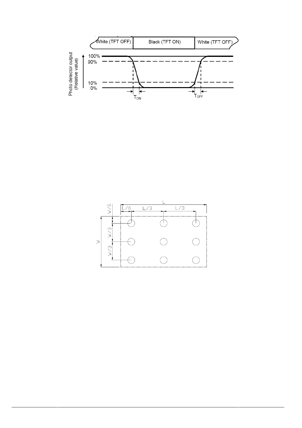
Note4: Definition of Response time
For TN LCM,t he response time is defined as the LCD optical switching time interval between “White”
state and “Black” state. Rise time (T r ) is the time between photo detector output intensity changed from
90% to 10%. And fall time (T f ) is the time between photo detector output intensity changed from 10% to
90%.
URL: www.topwaydisplay.com
Document Name: LMT080ENEFWA-Manual-Rev0.1.DOC
13
TOPWAY
LCD Module User Manual
LMT080ENEFWA
-
Fig3. Response Time Testing(TN)
Note5: Definition of color chromaticity (CIE1931)
Color coordinates measured at center point of LCD.
Note6: Definition of Luminance Uniformity
Active area is divided into 9 measuring areas (Refer Fig.5). Every measuring point is placed at the
center of each measuring area.
Luminance Uniformity (U) = Lmin/ Lmax
Lmax: The measured Maximum luminance of all measurement position.
Lmin: The measured Minimum luminance of all measurement position.
L-------Active area length; W----- Active area width
Fig5. Luminance Uniformity Measurement Locations(9 points)
Note7: Definition of Luminance:
Measure the luminance of white state at center point.
URL: www.topwaydisplay.com
Document Name: LMT080ENEFWA-Manual-Rev0.1.DOC
14
TOPWAY
-
LCD Module User Manual
LMT080ENEFWA
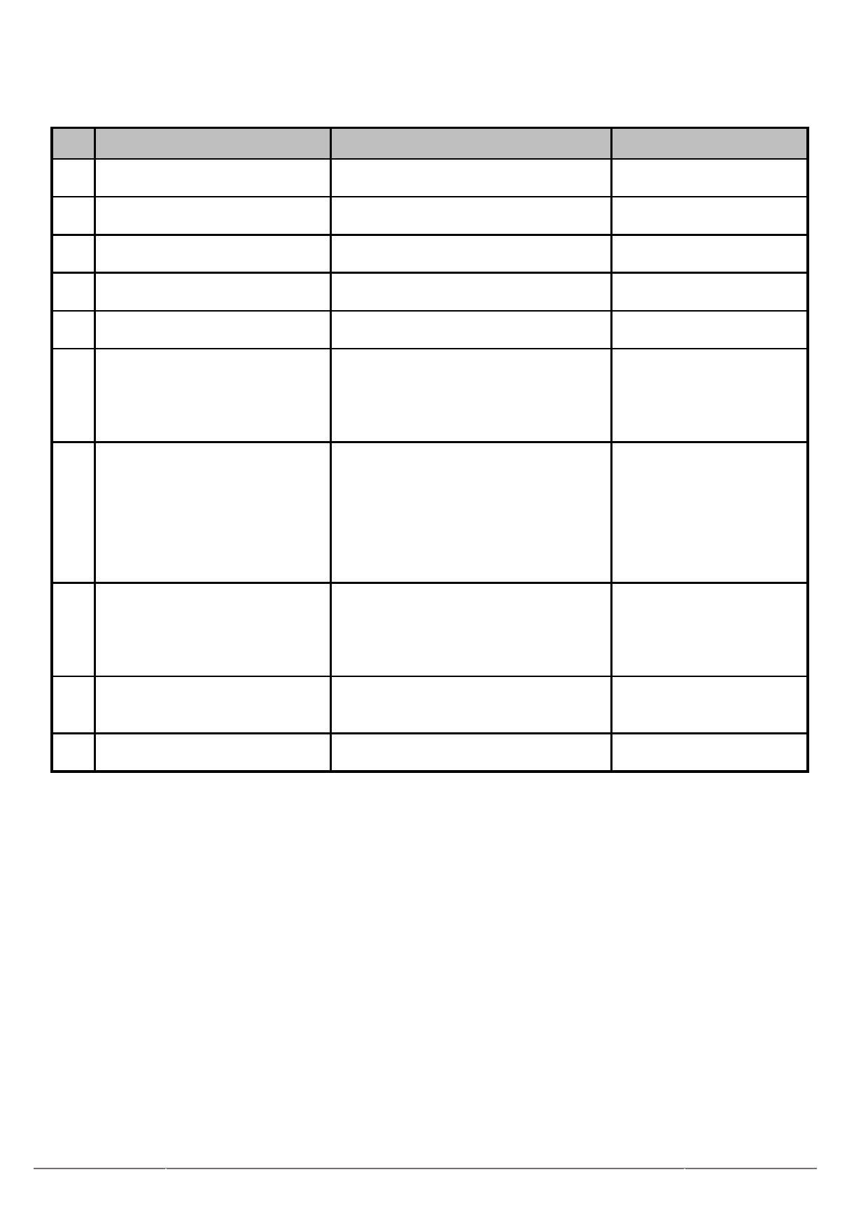
8. Reliability Test
No
Test Item
Condition
Remarks
1
High Temperature Operation
IEC60068-2-1:2007
+70 ℃ , 240H
GB2423.2-2008
2
Low Temperature Operation
IEC60068-2-1:2007
-20 ℃ , 240H
GB2423.1-2008
3
High Temperature Storage
IEC60068-2-1:2007
+80 ℃ , 240H
GB2423.2-2008
4
Low Temperature Storage
IEC60068-2-1:2007
-30 ℃ , 240H
GB2423.1-2008
5
Operation at High Temperature
IEC60068-2-78 :2001
and Humidity
+60 ℃ , 90%RH , 240H
GB/T2423.3 — 2006
Start with cold
-30 ℃ , 30min~80 ℃ , 30min , change temperature,
6
Thermal Shock (non-operation)
End with high temperature,
time : 5min , 100cycles
IEC60068-2-14:1984,GB2
423.22-2002
C=150pF , R=330Ω , 5point/panel
Air : ±8kv , 5times ;
7
ESD
IEC61000-4-2:2001
Contact : ±4kv , 5times ;
GB/T17626.2-2006
( Environment : 15 ℃ ~35 ℃ ,
30%~60% , 86Kpa~106Kpa )
Frequency range:10~55Hz
Stroke:1.5mm
8
Vibration Test
Sweep:10Hz~55Hz~10Hz
IEC60068-2-6:1982
2 hours for each direction of X.Y.Z.
GB/T2423.10 — 1995
(6 hours for total)
5-20-200HZ , PSD : 0.01-0.01-0.001
9
Package Vibration
GB/T 4857.23-2012
Total:0.781g2/HZ, x/y/z 30min )
10 Package Drop Test
Height: 60cm,1 corner, 3edges, 6
IEC60068-2-32:1990
surfaces
GB/T2423.8 — 1995
Table 8.1 RA test condition
Note1: Temperature is the ambient temperature of sample
Note2: Before cosmetic and function test, the product must have enough recovery time, at least 2 hours at room
temperature.
Note3: In the standard condition, there shall be no practical problem that may affect the display function. After the
reliability test, the product ’ s function only be guaranteed, but not for all of the cosmetic specification.
URL: www.topwaydisplay.com
Document Name: LMT080ENEFWA-Manual-Rev0.1.DOC
15
TOPWAY
-
LCD Module User Manual
LMT080ENEFWA
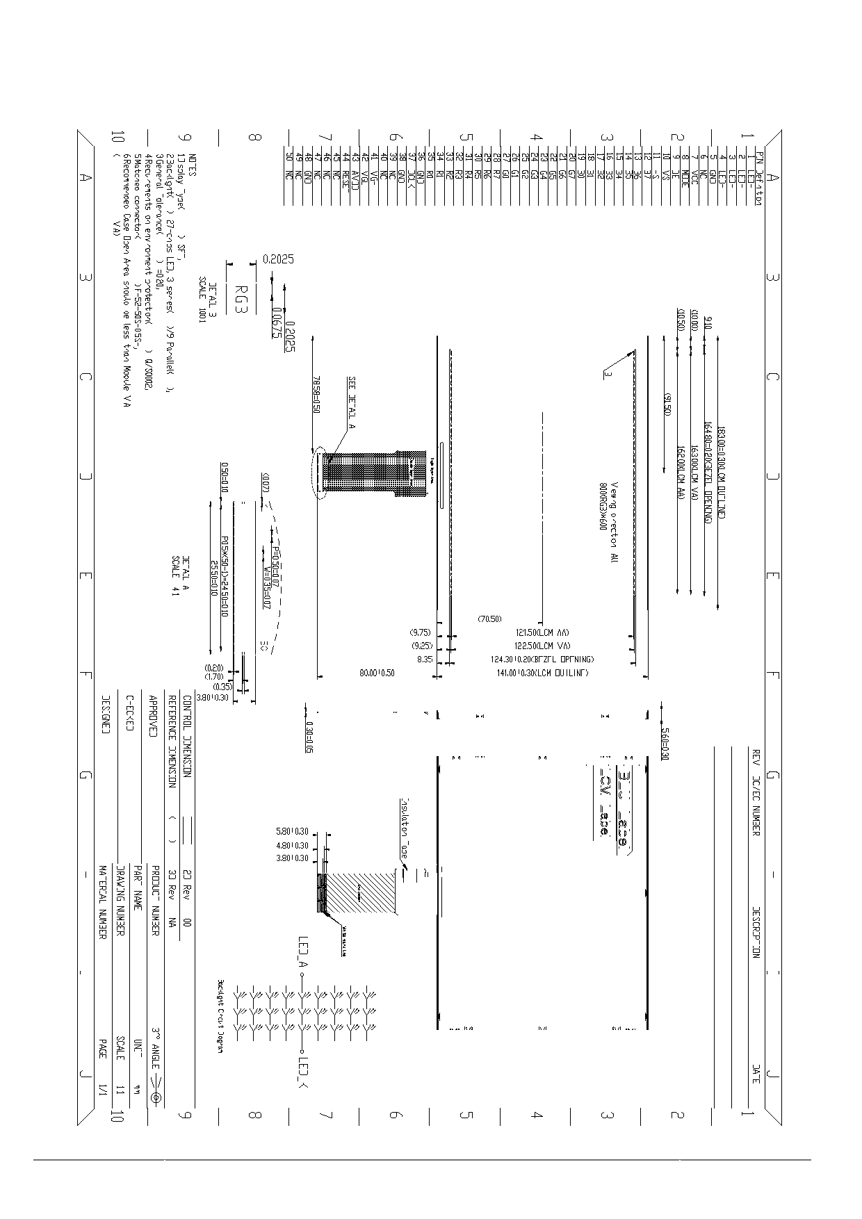
9. Mechanical Drawing
URL: www.topwaydisplay.com
Document Name: LMT080ENEFWA-Manual-Rev0.1.DOC
16

TOPWAY
LCD Module User Manual
LMT080ENEFWA
-
10. Precautions for Use of LCD Modules
10.1 Handling Precautions
(1) The display panel is made of glass. Do not subject it to mechanical shock by dropping it, etc.
(2) If the display panel is damaged and the liquid crystal fluid inside it leaks out be sure not to get any in your
mouth. If the fluid comes into contact with your skin or clothes promptly wash it off using soap and water.
(3) Do not apply excessive force to the display surface or the bezel since this may cause the color tone to vary.
(4) The polarizer covering the display surface of the LCD module is soft and easily scratched. Handle the
polarizer carefully.
(5) If the display surface is contaminated, breathe on the surface and gently wipe it with a soft dry cloth. If it is
still not completely clear use a moist cloth with one of the following solvents:
- Isopropyl alcohol
- Ethyl alcohol
Solvents other than those mentioned above may damage the polarizer. Specifically, do not use the
following:
- Water
- Ketone
- Aromatic solvents
(6) Do not disassemble the LCD Module.
(7) If powered off, do not apply the input signals.
(8) To prevent destruction of the module by static electricity, be careful to maintain an optimum work
environment.
(9) Be sure to ground your body when handling the LCD Modules.
(10) Tools used for assembly, must be properly grounded.
(11) To reduce the amount of static electricity generated, do not conduct assembly or other work under very low
humidity conditions.
(12) The LCD Module is covered with a film to protect the display surface, remove film slowly under the ionizer.
10.2 Storage precautions
(1) When storing the LCD modules avoid exposure to direct sunlight or to the light of fluorescent lamps.
(2) The LCD modules should be stored within the rated storage temperature range. The recommend condition
is: Temperature: 0 ~ 35 ℃ at normal humidity.
(3) The LCD modules should be stored in a room without acid, alkali or other harmful gas.
10.3 Transportation Precautions
The LCD modules should not be dropped or subject to violent mechanical shock during transportation. Also
they should avoid excessive pressure, water, high humidity and direct sunlight.
10.4 Screen saver Precautions
Not display the fixed pattern for a long time. Use a screen saver, if the fixed pattern is displayed on the screen
10.5 Safety Precautions
(1) When you waste damaged or unnecessary LCDs, it is recommended to crush LCDs into pieces and wash
them off with solvents such as acetone and ethanol, which should later be burned
(2) Be sure to turn off the power supply when inserting or disconnecting the LED backlight cable.
(3) LED driver should be designed to limit or stop its function when over current is detected on the LED.
URL: www.topwaydisplay.com
Document Name: LMT080ENEFWA-Manual-Rev0.1.DOC
18