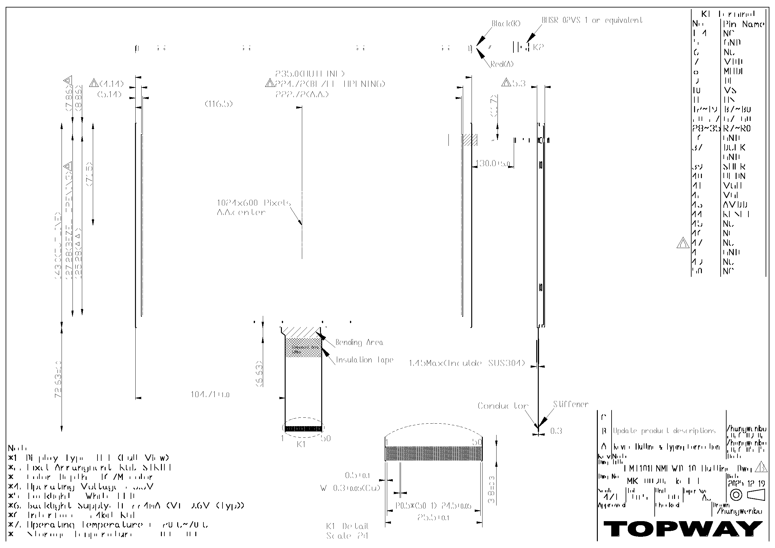
LMT101ENMFWD-10
LCD Module User Manual
Prepared by:
Checked by:
Approved by:
Heyuanlun
Date: 2026-09-04
Date:
Date:
Rev. Descriptions
Edit
Release Date
0.1
Preliminary
Zhangwenbo
2026-05-14
0.2
Update production description
Heyuanlun
2026-09-04
URL: www.topwaydisplay.com
Document Name: LMT101ENMFWD-10-Manual-Rev0.2.doc
Page: 1 of 13

TOPWAY
LCD Module User Manual
LMT101ENMFWD-10
Table of Content
1. General Specification........................................................................................................... 3
2. Block Diagram......................................................................................................................3
3. Terminal Function.................................................................................................................4
3.1 K1 TFT Input Terminal(089H50-000100-G2-R or equivalent)........................................ 4
3.2 K2 Backlight Terminal (SM02B-BHSS-1-TB or equivalent)............................................5
4. Absolute Maximum Ratings..................................................................................................5
5. Electrical Characteristics......................................................................................................6
5.1 DC Characteristics for Panel Driving..............................................................................6
5.2 DC Characteristics for Backlight Driving........................................................................ 6
5.3 Recommended Power ON/OFF Sequence....................................................................7
6. Timing Characteristics..........................................................................................................8
6.1 24-bit Parallel RGB Data Input Format.......................................................................... 8
6.2 Data input timing table................................................................................................... 8
6.3 TTL AC Characteristics.................................................................................................. 9
7. Optical Characteristics....................................................................................................... 10
8. LCD Module Design and Handling Precautions................................................................. 12
URL: www.topwaydisplay.com
Document Name: LMT101ENMFWD-10-Manual-Rev0.2.doc
Page: 2 of 13
TOPWAY
LCD Module User Manual
LMT101ENMFWD-10
1. General Specification
Screen Size(Diagonal) :
10.1”
Active Area :
222.72x 125.28(mm)
Number of dots :
1024(RGB) x600
Pixel Pitch :
0.2175x0.2088(mm)
Color Depth:
16.7M
Display Technology :
a-Si
Signal Interface:
RGB 24bit
Display Mode:
Normal Black, Transmissive
Outline Dimension:
235.0x143.0x5.3(mm)
(see outline drawing for details)
Pixel Configuration:
R.G.B. Vertical Stripe
Viewing Direction :
Full
Backlight :
White LEDs
Operating Temperature :
-20 ~ +70°C
Storage Temperature :
-30 ~ +80°C
Note:
*1. Color tone may slightly change by temperature and driving condition.
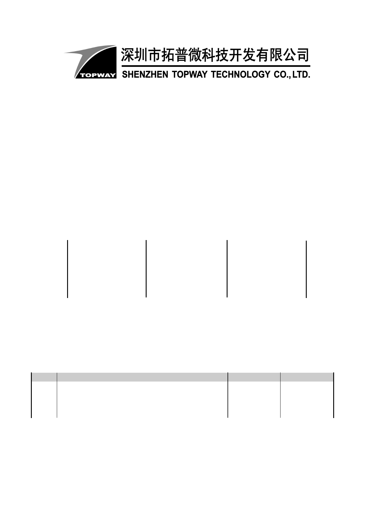
2. Block Diagram
LEDA,LEDK
Backlight Circuit
VDD, GND, AVDD
VGH, VGL
10.1’’ TFT Panel
DCLK
DE, HS, VS
MODE
R0~R7, G0~G7, B0~B7
Source Driver
URL: www.topwaydisplay.com
Document Name: LMT101ENMFWD-10-Manual-Rev0.2.doc
Page: 3 of 13
TOPWAY
LCD Module User Manual
LMT101ENMFWD-10
3. Terminal Function
3.1
K1 TFT Input Terminal(089H50-000100-G2-R or equivalent)
Pin No. Pin Name I/O
Descriptions
Comment
1
NC
-
2
NC
-
No connection
3
NC
-
4
NC
-
5
GND
P Power GND (0V)
6
NC
- No connection
7
VDD
P Digital Power
DE/SYNC mode select
8
MODE
I MODE=H: DE mode
Note 1
MODE=L : SYNC mode
9
DE
I Data input enable
10
VS
I Vertical Sync Input
11
HS
I Horizontal Sync Input
12
B7
I
:
:
I 8bit Data for Blue
19
B0
I
20
G7
I
:
:
I 8bit Data for Green
27
G0
I
28
R7
:
:
I 8bit Data for Red
35
R0
36
GND
P Power GND (0V)
37
DCLK
I Latch data at falling edge
38
GND
P Power GND (0V)
39
SHLR
I Left or right display control
Note 2
40
UPDN
I UP/down display control
Note 2
41
VGH
P Positive power for TFT
42
VGL
P Negative power for TFT
43
AVDD
P Analog power
44
RESET
I Global reset pin
45
NC
-
46
NC
- No connection
47
NC
-
48
GND
P Power GND (0V)
49
NC
-
No connection
50
NC
-
Note1: I/O definition: I---Input, O---Output, P---Power/Ground, N---No connection
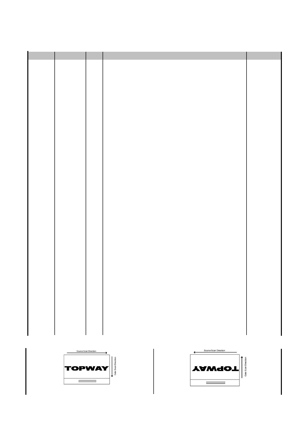
Note2: Scan direction is shown as below (PCB at down side):
L/R=1,U/D=0
L/R=0,U/D=1
URL: www.topwaydisplay.com
Document Name: LMT101ENMFWD-10-Manual-Rev0.2.doc
Page: 4 of 13
TOPWAY
LCD Module User Manual
LMT101ENMFWD-10
3.2
K2 Backlight Terminal (SM02B-BHSS-1-TB or equivalent)
NO
Symbol I/O Description
Comment
1
LEDK
P
LED driving cathode (low voltage)
Black
2
LEDA
P
LED driving anode (high voltage)
Red
Note1: I/O definition: I---Input, O---Output, P---Power/Ground, N---No connection
4. Absolute Maximum Ratings
Items
Symbol
Min.
Max.
Unit Condition
Power Voltage
VDD
-0.3
3.96
V
Input voltage
V IN
-0.3
3.96
V
Note1
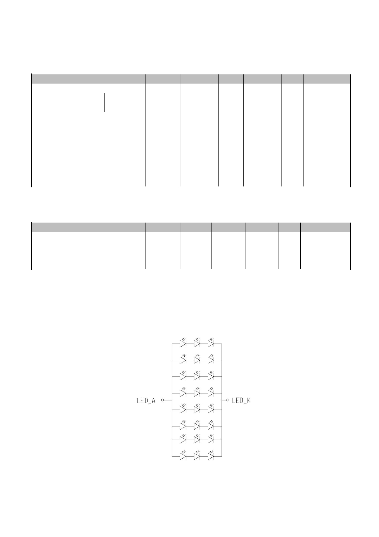
LED power supply Voltage
BLK
/
/
V
Operating Temperature
Top
-20
70
℃
Note2 、 Note3
Storage Temperature
Tst
-30
80
℃
-
≤ 95
%
Ta≤40 ℃
Relative Humidity
-
≤ 85
%
40 ℃ < Ta≤50 ℃
Note1
RH
-
≤ 55
%
50 ℃ < Ta≤60 ℃
-
≤ 36
%
60 ℃ < Ta≤70 ℃
Absolute Humidity
AH
-
≤ 70
g/m³ Ta > 70 ℃
Note1: Input voltage include REVERSE
Note2: Ta means the ambient temperature.
It is necessary to limit the relative humidity to the specified temperature range.
Condensation on the module is not allowed.
Note3: The absolute maximum rating values of this product are not allowed to be exceeded at any times.
When exceeded the maximum ratings, the characteristics of the module may not be recovered, or in
an extreme condition, the module may be permanently destroyed.
URL: www.topwaydisplay.com
Document Name: LMT101ENMFWD-10-Manual-Rev0.2.doc
Page: 5 of 13
TOPWAY
LCD Module User Manual
LMT101ENMFWD-10
5. Electrical Characteristics
5.1
DC Characteristics for Panel Driving
VCC=3.3V, GND=0V,T op =25°C
Items
Symbol
MIN.
TYP.
MAX.
Unit Remark
Supply Voltage
VDD
3.0
3.3
3.6
V
Input Signal Voltage Low Level
VIL
GND
-
0.2xVDD
V
High Level
VIH
0.8xVDD
-
VDD
V
VDD
3.0
3.3
3.6
V
IVDD
-
TBD
TBD
mA
AVDD
10.6
10.8
11.0
V
Power supply
IAVDD
-
TBD
TBD
mA
VGH
19.5
20.0
20.5
V
White
pattern
IVGH
-
TBD
TBD
mA
VGL
-9.5
-9.0
-8.5
V
IVGL
-
TBD
TBD
mA
Note: Input Signal Voltage include MODE,SHLR,UPDN,RESET.
5.2
DC Characteristics for Backlight Driving
T op =25°C
Items
Symbol
MIN.
TYP.
MAX. Unit Remark
Forward Current
IF
-
224
-
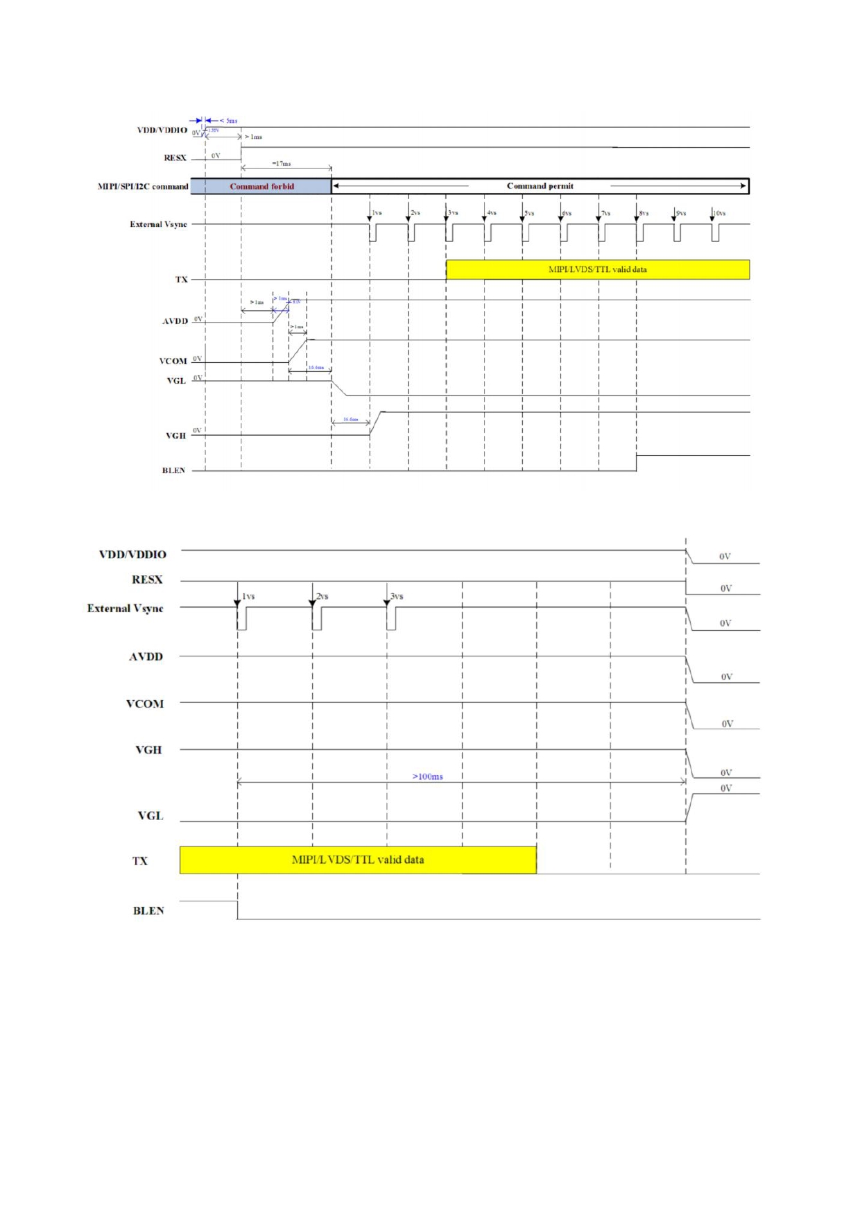
mA 24 LEDs
Forward Current Voltage
VF
8.7
9.6
10.2
V (3 LED
Backlight Power Consumption
WBL
-
2150.4
-
mW Parallel,8
LED life time
-
-
50000
-
Hrs LED Serial)
Note1: I F is defined for total current
Note2: Optical performance should be evaluated at Ta=25 ℃ only.
Note3: If LED is driven by high current, high ambient temperature & humidity condition,The life time of
LED will be reduced.
Note4: Operating life means brightness goes down to 50% of initial brightness. Typical operating life
time is estimated data.
URL: www.topwaydisplay.com
Document Name: LMT101ENMFWD-10-Manual-Rev0.2.doc
Page: 6 of 13
TOPWAY
LCD Module User Manual
LMT101ENMFWD-10
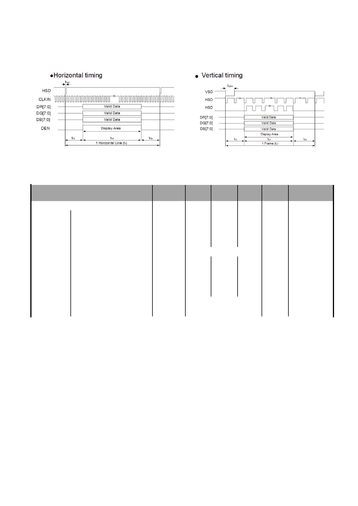
5.3 Recommended Power ON/OFF Sequence
Figure 5.3.1 Power ON Sequence
Figure 5.3.2 Power OFF Sequence
Note1: The low level of these signals and analog powers are GND level.
Note2: All of the power and signals should be kept at GND level before power on. If there are residual
voltages on them, the LCD might not work properly.
Note3: Keep backlight turned off until the display has stabilized.
URL: www.topwaydisplay.com
Document Name: LMT101ENMFWD-10-Manual-Rev0.2.doc
Page: 7 of 13
TOPWAY
LCD Module User Manual
LMT101ENMFWD-10
6. Timing Characteristics
6.1
24-bit Parallel RGB Data Input Format
Figure 6.1.1 24-bit parallel RGB mode input timing
6.2
Data input timing table
VCC=3.3V, GND=0V, Ta=25 ℃
Parameter
Symbol Min
Typ
Max
Unit
Remark
CLK frequency
Fclk
TBD
51.2
TBD MHz Tclk=1/Fclk
Horizontal Total
tht
TBD
1344 TBD
Tclk
Horizontal Front Porch
thfp
TBD
160
TBD
Tclk
Horizontal
Horizontal Back Porch
thb
TBD
160
TBD
section
Hsync Pulse Width
ths
TBD
24
TBD
Valid Data Width
thd
1024
Tclk
Vertical Total
tvt
TBD
635
TBD
TH
Vertical Front Porch
tvfp
TBD
12
TBD
TH
Vertical
Vertical Back Porch
section
tvb
TBD
23
TBD
Vsync Pulse Width
tvs
TBD
2
TBD
Valid Data Width
tvd
600
TH
Frame rate
60
Hz
URL: www.topwaydisplay.com
Document Name: LMT101ENMFWD-10-Manual-Rev0.2.doc
Page: 8 of 13
TOPWAY
LCD Module User Manual
LMT101ENMFWD-10
6.3
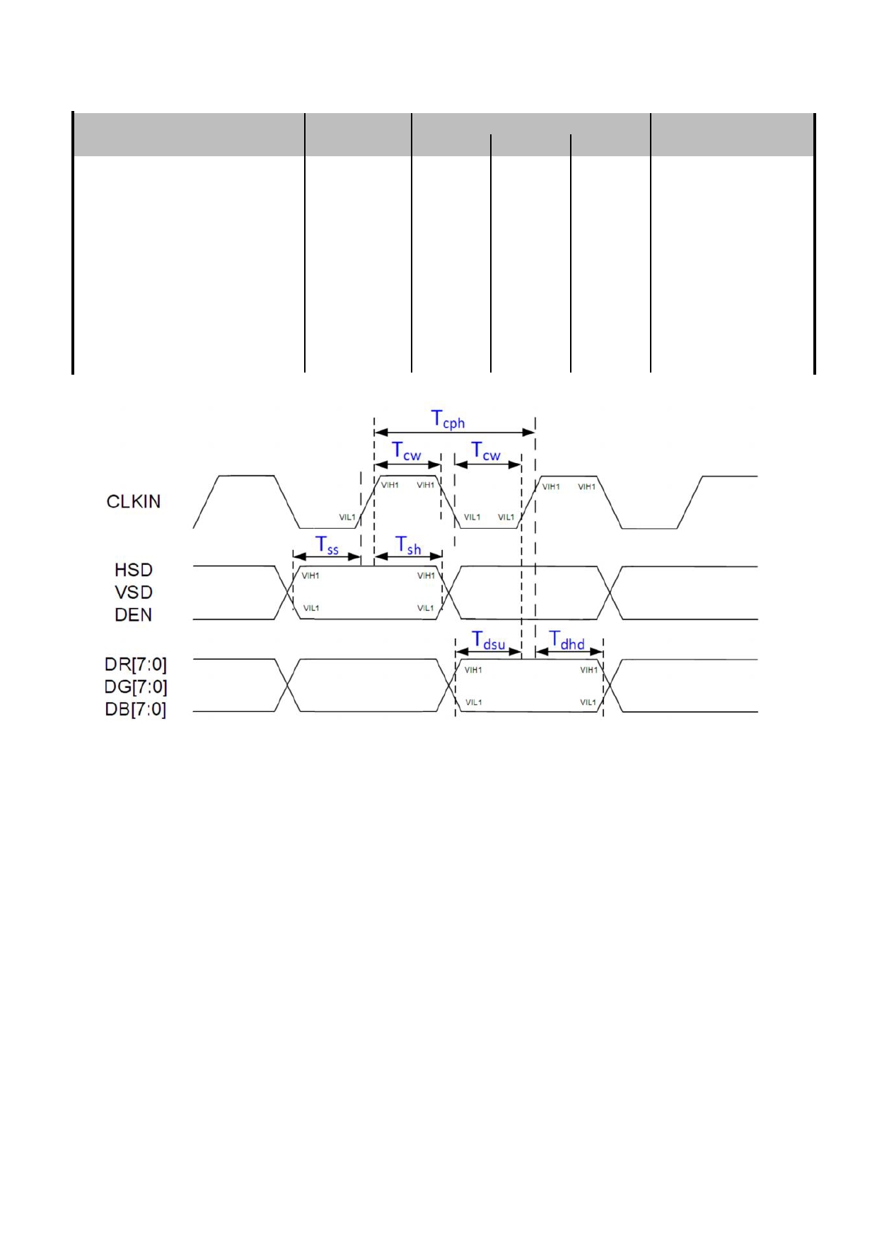
TTL AC Characteristics
Spec.
Parameter
Symbol
MIN.
TYP.
MAX.
Unit
CLKIN period
T cph
14
-
-
ns
CLKIN duty ratio
Tcw
40
50
60
%
Data setup time
Tdsu
5
-
-
ns
Data hold time
Tdhd
5
-
-
ns
VSD setup time
T ss
5
-
-
ns
VSD hold time
T sh
5
-
-
ns
HSD setup time
T ss
5
-
-
ns
HSD hold time
T sh
5
-
-
ns
DEN setup time
T ss
5
-
-
ns
DEN hold time
T sh
5
-
-
ns
Table 6.3.1 TTL mode AC electrical characteristics
Figure 6.3.2 Input signal timing
URL: www.topwaydisplay.com
Document Name: LMT101ENMFWD-10-Manual-Rev0.2.doc
Page: 9 of 13
TOPWAY
LCD Module User Manual
LMT101ENMFWD-10
7. Optical Characteristics
Item
Symbol Condition MIN TYP MAX
Unit
Remark
θ T
80
89
-
θ B
80
89
-
Viewing angle
CR ≥ 10
degree
Note2,3
θ L
80
89
-
θ R
80
89
-
Contrast Ratio
CR
θ=0 o
800
1000
-
Note3
T ON
Response Time
25 ℃
-
30
40
ms
Note4
T OFF
x
0.269
0.319
0.369
White
-
y
0.287
0.337
0.387
x
0.561
0.611
0.661
Red
-
y
Backlight is
0.313
0.363
0.413
Chromaticlty
on
Note1,5
x
0.282
0.332
0.382
Green
-
y
0.506
0.556
0.606
x
0.104
0.154
0.204
Blue
-
y
0.040
0.090
0.140
Uniformity
U
75
-
%
Note6
NTSC
-
45
50
-
%
Note5
Luminance
L
280
350
-
cd/m 2
Note7
Test Conditions:
1. IF= XXmA, and the ambient temperature is 25 ℃ ..
2. The test systems refer to Note 1 and Note 2.
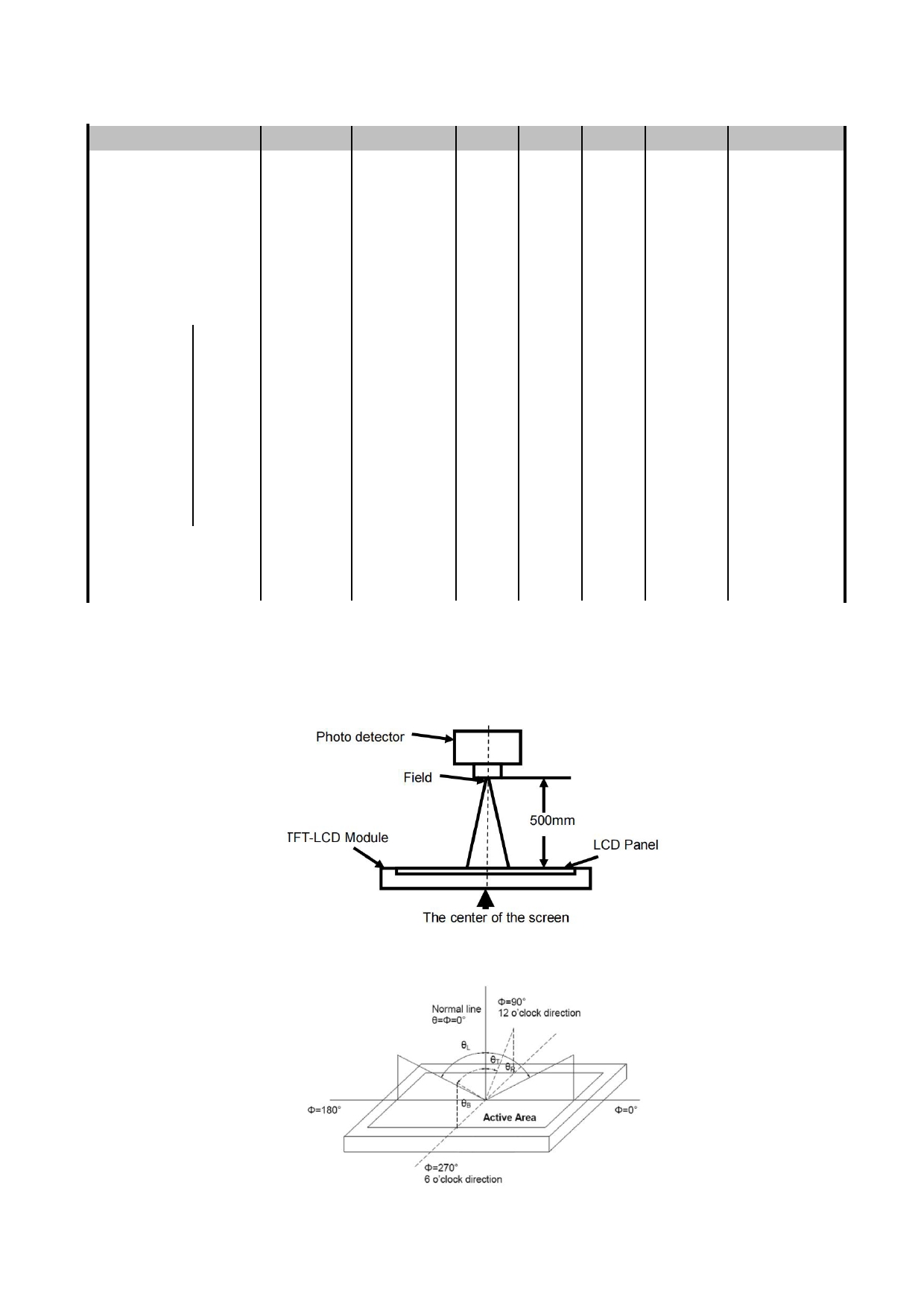
Note1: Definition of optical measurement system.
The optical characteristics should be measured in dark room. After 5 Minutes operation, the optical
characteristics are measured at the center point of the LCD screen.
Measurement Set Up
Note2: Definition of viewing angle range and measurement system. Viewing angle is measured at the center
point of the LCD 。
Measurement viewing angle
URL: www.topwaydisplay.com
Document Name: LMT101ENMFWD-10-Manual-Rev0.2.doc
Page: 10 of 13
TOPWAY
LCD Module User Manual
LMT101ENMFWD-10
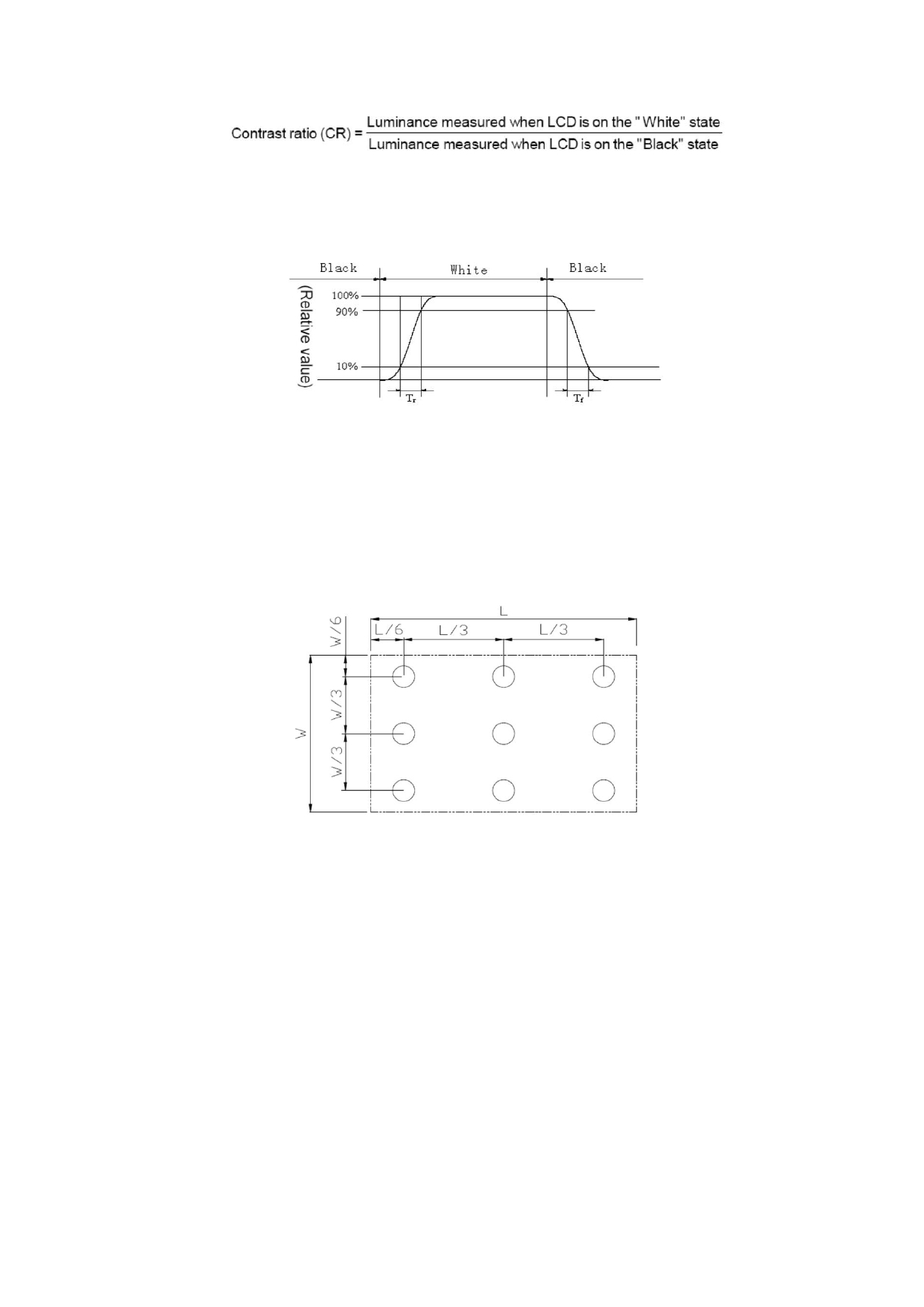
Note3: Definition of contrast ratio
Note4: Definition of Response time
For SFT LCM, the response time is defined as the LCD optical switching time interval between
“ White ” state and “ Black ” state. Rise time (Tr) is the time between photo detector output
intensity changed from 10% to 90%. And fall time (Tf) is the time between photo detector output
intensity changed from 90% to 10%.
Response Time Testing(SFT)
Note5: Definition of color chromaticity (CIE1931)
Color coordinates measured at center point of LCD.
Note6: Definition of Luminance Uniformity
Active area is divided into 9 measuring areas (Refer Fig.5). Every measuring point is placed at the
center of each measuring area.
Luminance Uniformity (U) = Lmin/ Lmax
Lmax: The measured Maximum luminance of all measurement position.
Lmin: The measured Minimum luminance of all measurement position.
L-------Active area length; W----- Active area width
Luminance Uniformity Measurement Locations(9 points)
Note7: Definition of Luminance:
Measure the luminance of white state at center point .
URL: www.topwaydisplay.com
Document Name: LMT101ENMFWD-10-Manual-Rev0.2.doc
Page: 11 of 13

TOPWAY
LCD Module User Manual
LMT101ENMFWD-10
8. LCD Module Design and
8. 液晶显示模块设计和使用须知
Handling Precautions
- Please ensure V0, VCOM is adjustable, to enable LCD module get - 请注意 V0, VCOM 的设定 , 以确保液晶显示模块在不同
the best contrast ratio under different temperatures, view angles
的使用温度下以及在不同的视角和位置观察模块显
and positions.
示,均能达到最佳对比度,请务必将应用电路上设置
为对比度可调。
- Normally display quality should be judged under the best contrast - 请注意液晶显示模块的显示品质判定是指在正常对比
ratio within viewable area. Unexpected display pattern may com out
度下以及视窗 (V.A) 范围内进行的,非正常对比度下液
under abnormal contrast ratio.
晶可能会出现非预期的显示不良,应注意区分。
- Never operate the LCD module exceed the absolute maximum
ratings.
- 请勿在最大额定值以外使用液晶显示模块。
- Never apply signal to the LCD module without power supply.
( No Hot-plugging )
- 请勿在没有接通电源的条件下,给液晶显示模块输送
- WARNING! Be aware of (if any) frame grounding of the LCD
信号。(禁止热插拔)
Module connection with the system which may cause safety
issue(e.g. electric shock,etc).
- 警告!使用前需评估液晶显示模块的金属框架 / 壳体地
- Keep signal line as short as possible to reduce external noise
( 如有 ) 与整机关系和安全性 ( 如:漏电安全性,等 ) 。
interference.
- IC chip (e.g. TAB or COG) is sensitive to light. Strong light might - 请尽可能缩短信号线的连接,以避免对液晶显示模块
cause malfunction. Light sealing structure casing is recommended.
的信号干扰。
- Make sure there is enough space (with cushion) between case and - 集成电路因 IC 芯片 ( 如 TAB 或 COG) 对紫外线极为敏
LCD panel, to prevent external force passed on to the panel;
感,强光环境下可能会引起液晶显示模块功能失效,
otherwise that may cause damage to the LCD and degrade its
故应采用不透光的外壳。
display result.
- 请在液晶显示模块与外壳之间保留足够的空间 ( 可使用
- Avoid showing a display pattern on screen for a long time
衬垫 ) ,以缓冲外力对液晶显示模块的损坏或因受力不
(continuous ON segment).
均而产生的显示不匀等异常现象。
- LCD module reliability may be reduced by temperature shock.
- 避免液晶显示屏在某一画面下长时间点亮,否则有出
- When storing and operating LCD module, avoids exposure to direct
现残影的风险;请通过软件每隔一段时间改变一次画
sunlight, high humidity, high or low temperature. They may damage
面。
or degrade the LCD module.
- 液晶显示模块的可靠性可能因温度冲击而降低。
- Never leave LCD module in extreme condition (max./min
storage/operate temperature) for more than 48hr.
- 请勿在阳光直射、高湿、高温或低温下储存和使用液
- Recommend LCD module storage conditions is 0 ℃ ~40 ℃
晶显示模块,这将造成液晶显示模块的损坏或失效。
<80%RH.
- LCD module should be stored in the room without acid, alkali and
harmful gas.
- 请勿在极限环境 ( 最大 / 最小存储 / 工作温度 ) 下使用或
- Avoid dropping & violent shocking during transportation, and no
放置液晶显示模块超过 48 小时以上。
excessive pressure press, moisture and sunlight.
- LCD module can be easily damaged by static electricity. Please - 液晶显示模块建议存储条件为 : 0 ℃ ~40 ℃ <80%RH 。
maintain an optimum anti-static working environment to protect the
LCD module. (eg. ground the soldering irons properly)
- 请勿让液晶显示模块存储于带有 酸性 , 碱性 , 有害气
- Be sure to ground the body when handling LCD module.
体环境之中。
- Only hold LCD module by its sides. Never hold LCD module by - 在运输过程中 , 请勿让液晶显示模块跌落与猛烈震动 ,
applying force on the heat seal or TAB.
同时避免 异常挤压 , 高湿度 , 与 阳光照射
- When soldering, control the temperature and duration avoid - 液晶显示模块极易受静电损坏,请务必保证液晶显示
damaging the backlight guide or diffuser which might degrade the
模块在防静电的工作环境中使用或保存。 ( 如 : 烙铁正
display result such as uneven display.
确接地 , 等 )
- Never let LCD module contact with corrosive liquids, which might
cause damage to the backlight guide or the electric circuit of LCD
module.
- 拿取液晶显示模块时需注意操作人员的接地情况。
- Only clean LCD with a soft dry cloth, Isopropyl Alcohol or Ethyl
Alcohol. Other solvents (e.g. water) may damage the LCD.
- 请手持液晶显示模块的边沿取放模块,防止热压纸或
- Never add force to components of LCD module. It may cause
TAB 部位受力。
invisible damage or degrade the module's reliability.
- 焊接液晶模块时,请注意控制烙铁的温度、焊接时
- When mounting LCD module, please make sure it is free from
间,以免烫坏导光板或偏光片,导致显示不匀等不良
twisting, warping and bending.
现象发生。
- Do not add excessive force on surface of LCD, which may cause
URL: www.topwaydisplay.com
Document Name: LMT101ENMFWD-10-Manual-Rev0.2.doc
Page: 12 of 13

TOPWAY
LCD Module User Manual
LMT101ENMFWD-10
the display color change abnormally.
- 请勿使用洗板水等腐蚀性液体接触液晶模块,以免腐
- LCD panel is made with glass. Any mechanical shock (e.g.
蚀导光板或模块电路。
dropping from high place) will damage the LCD module.
- Protective film is attached on LCD screen. Be careful when peeling - 仅可使用柔软的干布 , 异丙醇或乙醇清洁液晶屏表
off this protective film, since static electricity may be generated.
面,其他任何溶剂 ( 如 : 水 ) 都有可能损坏液晶模块。
- Polarizer on LCD gets scratched easily. If possible, do not remove
LCD protective film until the last step of installation.
- 请勿挤压液晶显示模块上的元器件,以避免产生潜在
- When peeling off protective film from LCD, static charge may cause
的损坏或失效而影响产品可靠性。
abnormal display pattern. The symptom is normal, and it will turn
back to normal in a short while.
- 装配液晶显示模块时,请务必注意避免液晶显示模块
- LCD panel has sharp edges, please handle with care.
的扭曲或变形。
- Never attempt to disassemble or rework LCD module.
- 请勿挤压液晶显示屏表面,这将导致显示颜色的异
- If display panel is damaged and liquid crystal substance leaks out,
常。
be sure not to get any in your mouth, if the substance comes into - 液晶屏由玻璃制作而成,任何机械碰撞 ( 如从高处跌
contact with your skin or clothes promptly wash it off using soap
落 ) 均有可能损坏液晶显示模块。
and water.
- 液晶屏表面带有保护膜 , 揭除保护膜时需要注意可能
产生的静电。
- 因液晶显示屏表面的偏光片极易划伤,安装完成之前
请尽量不要揭下保护膜。
- 请缓慢揭除保护膜,在此过程中液晶显示屏上可能会
产生静电线,此为正常情况,可在短时间内消失。
- 请注意避免被液晶显示屏的边缘割伤。
- 请不要试图拆卸或改造液晶显示模块。
- 当液晶显示屏出现破裂 , 内部液晶液体可能流出 ; 相
关液体不可吞吃 , 绝对不可接触嘴巴 , 如接触到皮肤
或衣服 , 请使用肥皂与清水彻底清洗 .
Warranty
This product has been manufactured to our company’s specifications as a part for use in your company’s general
electronic products. It is guaranteed to perform according to delivery specifications. For any other use apart from general
electronic equipment, we cannot take responsibility if the product is used in medical devices, nuclear power control
equipment, aerospace equipment, fire and security systems, or any other applications in which there is a direct risk to
human life and where extremely high levels of reliability are required. If the product is to be used in any of the above
applications, we will need to enter into a separate product liability agreement.
- We cannot accept responsibility for any defect, which may arise form additional manufacturing of the product (including
disassembly and reassembly), after product delivery.
- We cannot accept responsibility for any defect, which may arise after the application of strong external force to the
product.
- We cannot accept responsibility for any defect, which may arise due to the application of static electricity after the
product has passed our company’s acceptance inspection procedures.
- When the product is in CCFL models, CCFL service life and brightness will vary according to the performance of the
inverter used, leaks, etc. We cannot accept responsibility for product performance, reliability, or defect, which may arise.
- We cannot accept responsibility for intellectual property of a third part, which may arise through the application of our
product to our assembly with exception to those issues relating directly to the structure or method of manufacturing of
our product.
URL: www.topwaydisplay.com
Document Name: LMT101ENMFWD-10-Manual-Rev0.2.doc
Page: 13 of 13