MODEL NO
:
LMT101GNMFWD
SPEC VERSION:
V1.0
ISSUED DATE:
2022-08-15
□ Preliminary Specification
◼ Final Product Specification
Customer :
Approved by
Notes
Topway Confirmed :
Prepared by
Checked by
Approved by
Dong Qiang
URL:
Document Name:LMT101GNFWD-Manual-Rev1.0(w_dwg)
Page: 1 of 18

TOPWAY
LCD Module User Manual
LMT101GNMFWD
Table of Contents
Table of Contents............................................................................................................................ 2
Record of Revision .......................................................................................................................... 3
1
General Specifications ............................................................................................................. 4
2
Input/Output Terminals ............................................................................................................. 5
3
Absolute Maximum Ratings ...................................................................................................... 7
4
Electrical Characteristics .......................................................................................................... 8
5
Timing Chart ............................................................................................................................ 9
6
Optical Characteristics ........................................................................................................... 13
7
Environmental / Reliability Test .............................................................................................. 16
8
Mechanical Drawing ............................................................................................................... 17
9
Precautions for Use of LCD Modules ..................................................................................... 18
URL:
Document Name:LMT101GNFWD-Manual-Rev1.0(w_dwg)
Page: 2 of 18
TOPWAY
LCD Module User Manual
LMT101GNMFWD
Record of Revision
Rev
Issued Date
Description
Editor
1.0
2022-08-15
First Release.
Dong Qiang
URL:
Document Name:LMT101GNFWD-Manual-Rev1.0(w_dwg)
Page: 3 of 18
TOPWAY
LCD Module User Manual
LMT101GNMFWD
1
General Specifications
Feature
Spec
Size
10.1 inch
Resolution
1024(RGB )× 600
Technology Type
a-Si TFT
Pixel Configuration
R.G.B. Vertical Stripe
Display Spec.
Pixel pitch(mm)
0.2175x0.2088
Display Mode
Transmissive, Normally White
Surface Treatment
AG
Viewing Direction
12 o’clock
Gray Scale Inversion Direction
6 o’clock
LCM (W x H x D) (mm)
235.00 x 143.00 x 5.6
Active Area(mm)
222.72 x 125.28
Mechanical
With /Without TSP
Without TSP
Characteristics
Matching Connection Type
Starconn:089H50-000100-G2-R
LED Numbers
24 LED
Weight (g)
TBD
Electrical
Interface
24 bit RGB
Characteristics
Color Depth
16.7M
Note 1: Viewing direction for best image quality is different from TFT definition. There is a 180
degree shift.
Note 2: Requirements on Environmental Protection: Q/S0002
Note 3: LCM weight tolerance: ± 5%
URL:
Document Name:LMT101GNFWD-Manual-Rev1.0(w_dwg)
Page: 4 of 18
TOPWAY
LCD Module User Manual
LMT101GNMFWD
2
Input/Output Terminals
Recommended connector: STARCONN 089H50-000100-G2-R
Pin
Symbol
I/O
Description
Remark
1
NC
-
No connection
2
NC
-
No connection
3
NC
-
No connection
4
NC
-
No connection
5
GND
P
Power GND
6
NC
-
No connection
7
VDD
P
Digital Power
DE/SYNC mode select
8
MODE
I
(“1”:DE “0”:SYNC)
Note1
9
DE
I
Data input enable
10
VS
I
Vertical sync input
11
HS
I
Horizontal sync input
12
B7
I
Blue data(MSB)
13
B6
I
Blue data
14
B5
I
Blue data
15
B4
I
Blue data
16
B3
I
Blue data
17
B2
I
Blue data
18
B1
I
Blue data
19
B0
I
Blue data(LSB)
20
G7
I
Green data(MSB)
21
G6
I
Green data
22
G5
I
Green data
23
G4
I
Green data
24
G3
I
Green data
25
G2
I
Green data
26
G1
I
Green data
27
G0
I
Green data(LSB)
28
R7
I
Red data(MSB)
29
R6
I
Red data
30
R5
I
Red data
31
R4
I
Red data
32
R3
I
Red data
33
R2
I
Red data
34
R1
I
Red data
35
R0
I
Red data(LSB)
36
GND
P
Power GND
37
DCLK
I
Latch at falling edge
38
GND
P
Power GND
39
SHLR
I
Left or right display control
Note2
40
UPDN
I
UP/down display control
Note3
41
VGH
P
Positive power for TFT
URL:
Document Name:LMT101GNFWD-Manual-Rev1.0(w_dwg)
Page: 5 of 18
TOPWAY
LCD Module User Manual
LMT101GNMFWD
42
VGL
P
Negative power for TFT
43
AVDD
P
Analog power
44
RESET
I
Global reset pin
45
NC
-
No connection
46
NC
-
No connection
47
DITHB
I
Dithering function
(“1”: 8bit “0”: bit)
Note4
48
GND
P
Power GND
49
NC
-
No connection
50
NC
-
No connection
BackLight Connector
Connector: JST BHSR-02VS-1
No
Symbol
I/O
Description
Wire Color
1
LEDA
P
LED driving anode (high voltage)
Red
2
LEDK
P
LED driving cathode (low voltage)
White
Note1: DE/SYNC mode select. Normally pull high.
When MODE=H: DE mode.
When MODE=L : SYNC mode.
Note2: Source Driver internal shift register is controlled by this pin as shown below:
Normally pull high.
SHLR=H: SO1 SO2 SO3•••SO1024. (Default)
SHLR=L: SO1024 SO1023 SO1022•••SO1.
Note3: Gate Driver Up/down scan setting. Normally pull low.
When UPDN=H: Reverse scan. G600 G599 G598•••G1.
When UPDN=L, normal scan. (Default) G1•••G600.
Note4: Dithering function enable control. Normally pull low.
When DITHER=H: Enable internal dithering function.
When DITHER=L: Disable internal dithering function.
URL:
Document Name:LMT101GNFWD-Manual-Rev1.0(w_dwg)
Page: 6 of 18
TOPWAY
LCD Module User Manual
LMT101GNMFWD
3
Absolute Maximum Ratings
GND=0V
Item
Symbol
Min
Max
Unit
Remark
Power Voltage
VCC
2.8
3.6
V
Positive power for TFT
VGH
-0.3
+42.0
V
Negative power for TFT
VGL
VGH-42
+0.3
V
Analog power
AVDD
-0.5
14.85
V
Operating Temperature
TOPR
-20
70
℃
Storage Temperature
TSTG
-30
80
℃
RH
--
≤ 95
%
Ta ≤ 40 ℃
--
≤ 85
%
40 ℃< Ta ≤ 50 ℃
Relative Humidity
Note1
--
≤ 55
%
50 ℃< Ta ≤ 60 ℃
--
≤ 36
%
60 ℃< Ta ≤ 70 ℃
--
≤ 24
%
70 ℃< Ta ≤ 80 ℃
Absolute Humidity
AH
--
≤ 70
g/m ³
Ta > 70 ℃
Note1: Ta means the ambient temperature.
It is necessary to limit the relative humidity to the specified temperature range.
Condensation on the module is not allowed.
URL:
Document Name:LMT101GNFWD-Manual-Rev1.0(w_dwg)
Page: 7 of 18
TOPWAY
LCD Module User Manual
LMT101GNMFWD
4
Electrical Characteristics
4.1 Driving TFT LCD Panel
GND=0V, Ta=25 ℃
Item
Symbol
Min
Typ
Max
Unit
Remark
Power Supply Voltage
VCC
3.0
3.3
3.6
V
Positive power for TFT
VGH
21
22
23
V
Negative power for TFT
VGL
-6.5
-7
-7.5
V
Analog power
AVDD
10.8
11
11.2
V
Current of VCC Power Supply
I VCC
-
30
-
mA
Note 1
Low Level
V IL
GND
-
0.3VCC
V
Input
Signal Voltage
High Level
V IH
0.7VCC
-
VCC
V
Note1: For each LED. To test the current dissipation, use “all Black Pattern ”
4.2 Recommended Driving Condition for Backlight
Ta=25 ℃
Item
Symbol
Min
Typ
Max
Unit
Remark
Forward Current
I F
-
560
-
mA
24LEDs
Forward Voltage
V F
8.0
9.6
10.2
V
(3 LED Serial, 8
LED Parallel,
Backlight Power Consumption
W BL
-
TBD
TBD
W
70mA for each)
Operating Life Time
-
-
30000
-
Hrs
IF =240mA
4.3 Power Consumption
AGND=GND=0V, Ta = 25 ℃
Item
Symbol
Condition
Min
Typ.
Max
Unit Remark
Digital Supply
Current
I VCC
VCC=3.3V
-
9.6
mA
Note1
Analog Supply
Note1
Current
I AVDD
AVDD=11V
-
40
mA
Gate On Current
I VGH
VGH=22V
-
TBD
mA
Note1
Gate Off Current
I VGL
VGL=-7.0V
-
TBD
mA
Note1
Pane l& Gamma
-
TBD
mW
Note1
Power Consumption
Backlight
TBD
mW
-
Total
-
TBD
mW
Note1
Note1: Tested at black pattern .
URL:
Document Name:LMT101GNFWD-Manual-Rev1.0(w_dwg)
Page: 8 of 18
TOPWAY
LCD Module User Manual
LMT101GNMFWD
5
Timing Chart
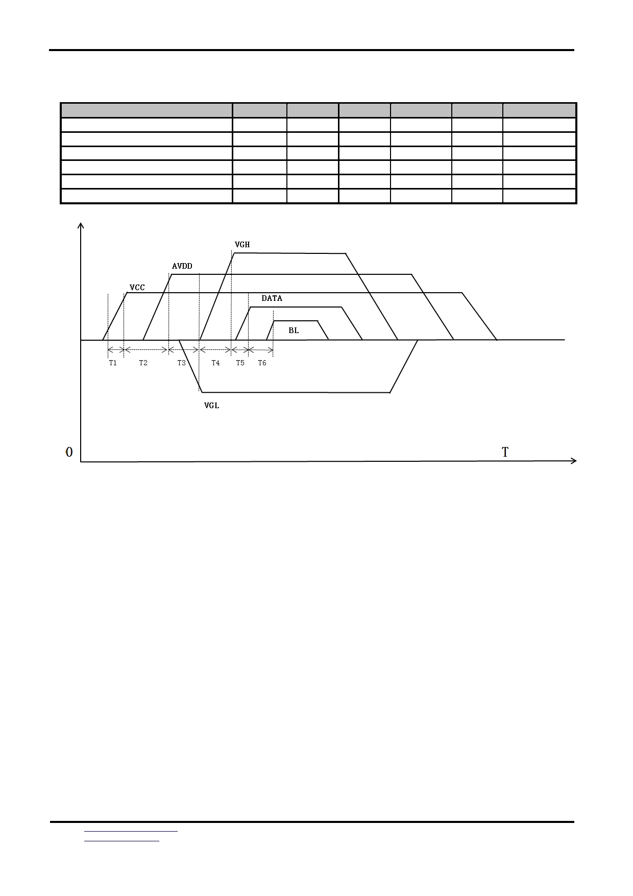
5.1 Power sequence
Item
Symbol
Min
Typ
Max
Unit
Remark
VCC 3.3V rising time
T1
0
-
20
ms
VCC to AVDD on time
T2
16.7
-
-
ms
AVDD to VGL on time
T3
>0
-
-
ms
VGL to VGH on time
T4
>0
-
-
ms
VGH to DATA on time
T5
>0
-
-
ms
DATA to BL on time
T6
>0
-
-
ms
Figure 5.1.1 Power on/off sequence
Note:1. Power on sequence: VCC ➔ AVDD ➔ VGL ➔ VGH ➔ DATA ON ➔ BACKLIGHT ON
2. Power off sequence: BACKLIGHT OFF ➔ DATA OFF ➔ VGH ➔ VGL ➔ AVDD ➔ VCC
3. When VCC turned on, the rising time T1 should less than 20ms.
4. AVDD stable to VCC stable time T2 should better longer than 1 frame time.
5. The power off sequence can be set according to power on settings.
URL:
Document Name:LMT101GNFWD-Manual-Rev1.0(w_dwg)
Page: 9 of 18
TOPWAY
LCD Module User Manual
LMT101GNMFWD
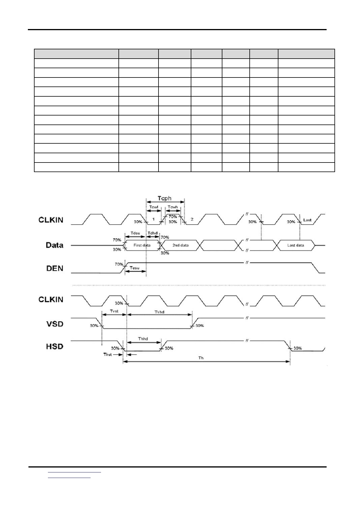
5.2.1 TTL mode AC electrical characteristics
Parameter
Symbol
Min
Typ
Max
Unit
Conditions
VDD Power on slew rate
Tpor
-
-
20
ms
From 0V to 90%
Reset pulse width
Tgrb
50
-
-
MHz
DCLK=65MHz
DCLK Cycle Time
Tcph
50
25
-
ns
DCLK Pulse Width
Tcw
40%
50%
60%
-
VSD Setup Time
Tvst
5
-
-
ns
VSD Hold Time
Tvhd
5
-
-
ns
HSD Setup Time
Thst
5
-
-
ns
HSD Hold Time
Thhd
5
-
-
ns
Data Setup Time
Tdsu
5
-
-
ns
Data to DCLK
Data Hold Time
Tdhd
5
-
-
ns
Data to DCLK
DE Setup Time
Tesu
5
-
-
ns
DE Hold Time
Tehd
5
-
-
ns
Table 5 . 2.1 Parallel 24-bit RGB mode
Figure 5.2.1 Input clock and data timing diagram
URL:
Document Name:LMT101GNFWD-Manual-Rev1.0(w_dwg)
Page: 10 of 18

TOPWAY
LCD Module User Manual
LMT101GNMFWD
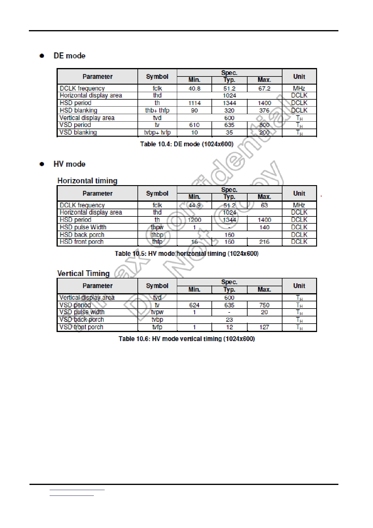
Figure 5.2.2 Vertical input timing
Figure 5.2.3 Horizontal input timing Diagram
URL:
Document Name:LMT101GNFWD-Manual-Rev1.0(w_dwg)
Page: 11 of 18
TOPWAY
LCD Module User Manual
LMT101GNMFWD
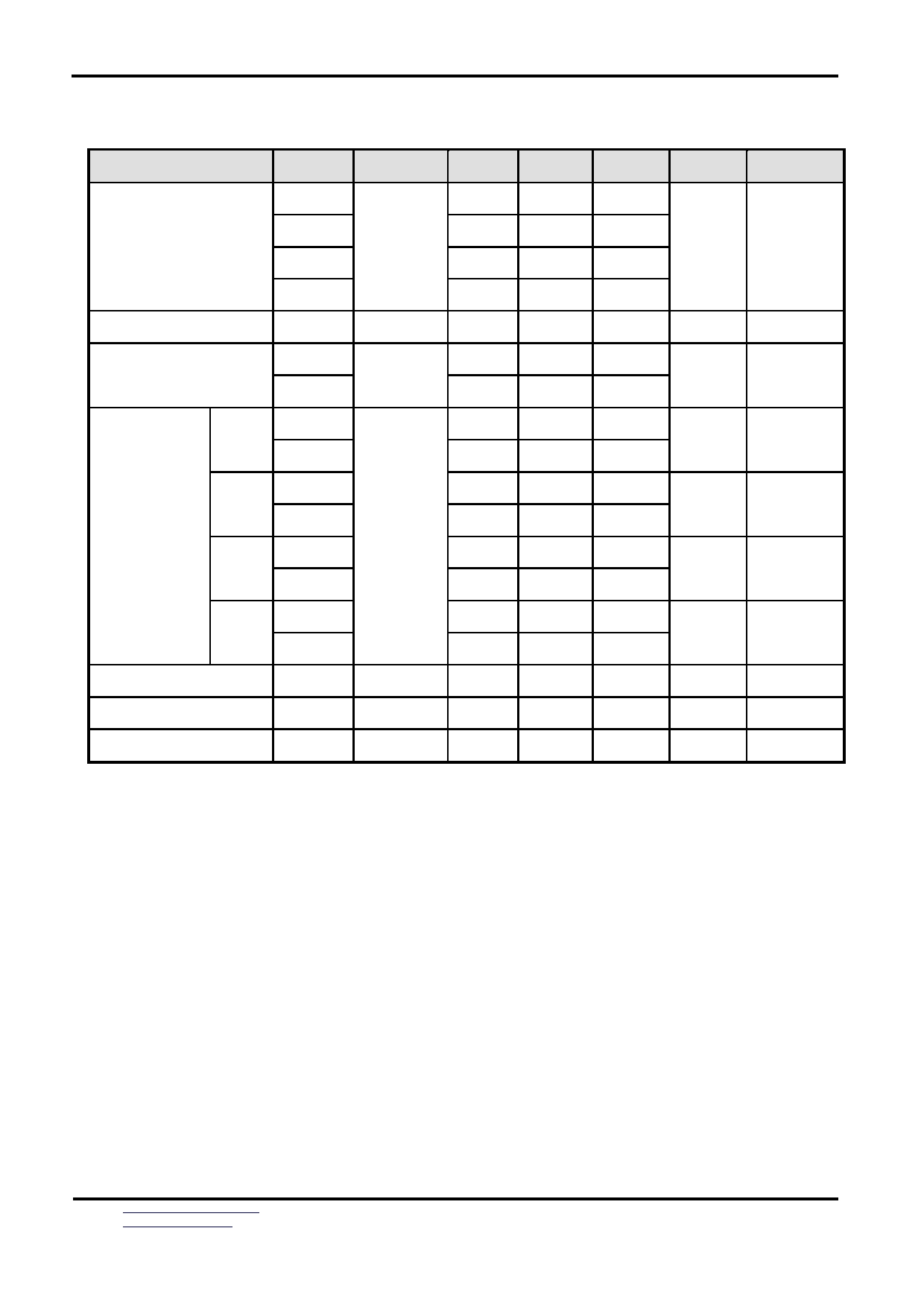
5.5 Timing characteristics
URL:
Document Name:LMT101GNFWD-Manual-Rev1.0(w_dwg)
Page: 12 of 18
TOPWAY
LCD Module User Manual
LMT101GNMFWD
6
Optical Characteristics
Item
Symbol Condition
Min
Typ
Max
Unit
Remark
θT
-
75
-
θB
-
80
-
View Angles
CR ≧ 10
Degree Note2,3
θL
-
80
-
θR
-
80
-
Contrast Ratio
CR
θ=0 o
400
500
Note 3
T ON
-
7
10
Response Time
25 ℃
ms
Note 4
T OFF
-
9
18
x
( 0.263 ) ( 0.313 ) ( 0.363 )
White
Note 1,5
y
( 0.279 ) ( 0.329 ) ( 0.379 )
x
( 0.524 ) ( 0.574 ) ( 0.624 )
Red
Note 1,5
y
( 0.285 ) ( 0.335 ) ( 0.385 )
Chromaticity
Backlight is
x
on
( 0.280 ) ( 0.330 ) ( 0.380 )
Green
Note 1,5
y
( 0.525 ) 0.575
( 0.625 )
x
( 0.108 ) ( 0.158 ) ( 0.208 )
Blue
Note 1,5
y
( 0.090 ) ( 0.140 ) ( 0.190 )
Uniformity
U
70
80
-
%
Note 6
NTSC
-
47
-
%
Note 5
Luminance
L
750
TBD
-
cd/m 2
Note 7
Test Conditions:
1. I F = 70 mA, and the ambient temperature is 25 ℃ .
2. The test systems refer to Note 1 and Note 2.
URL:
Document Name:LMT101GNFWD-Manual-Rev1.0(w_dwg)
Page: 13 of 18
TOPWAY
LCD Module User Manual
LMT101GNMFWD
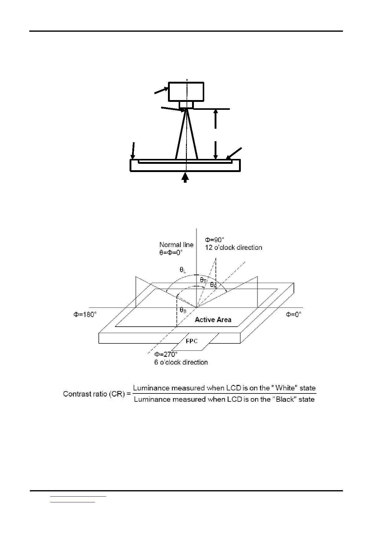
Note 1: Definition of optical measurement system.
The optical characteristics should be measured in dark room. The optical properties are measured
at the center point of the LCD screen. All input terminals LCD panel must be ground when
measuring the center area of the panel.
Photo detector
Field
500mm
TFT-LCD Module
LCD Panel
The center of the screen
Note 2: Definition of viewing angle range and measurement system.
viewing angle is measured at the center point of the LCD 。
Note 3: Definition of contrast ratio
“White state “: The state is that the LCD should drive by Vwhite.
“Black state”: The state is that the LCD should drive by Vblack.
Vwhite: To be determined
Vblack: To be determined.
URL:
Document Name:LMT101GNFWD-Manual-Rev1.0(w_dwg)
Page: 14 of 18
TOPWAY
LCD Module User Manual
LMT101GNMFWD
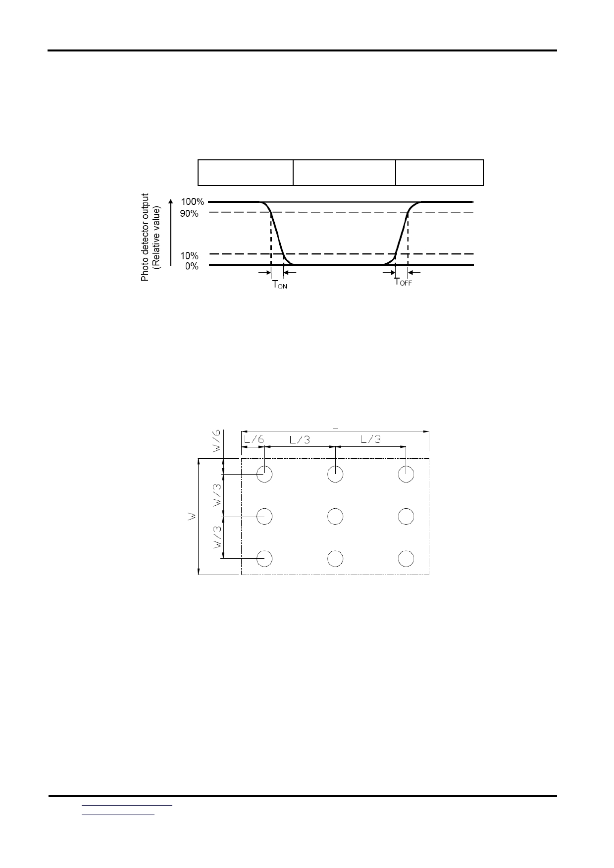
Note 4: Definition of Response time
The response time is defined as the LCD optical switching time interval between “White” state and
“Black” state. Rise time (T ON ) is the time between photo detector output intensity changed from 90%
to 10%. And fall time (T OFF ) is the time between photo detector output intensity changed from 10%
to 90%.
White (TFT off)
Black (TFT on)
White (TFT off)
Note 5: Definition of color chromaticity (CIE1931)
Color coordinates measured at center point of LCD.
Note 6: Definition of Luminance Uniformity
Active area is divided into 9 measuring areas (Refer Fig. 2). Every measuring point is placed at the
center of each measuring area.
Luminance Uniformity (U) = Lmin/ Lmax
L-------Active area length W ----- Active area width
Lmax: The measured Maximum luminance of all measurement position.
Lmin: The measured Minimum luminance of all measurement position.
Note 7: Definition of Luminance:
Measure the luminance of white state at center point.
URL:
Document Name:LMT101GNFWD-Manual-Rev1.0(w_dwg)
Page: 15 of 18
TOPWAY
LCD Module User Manual
LMT101GNMFWD
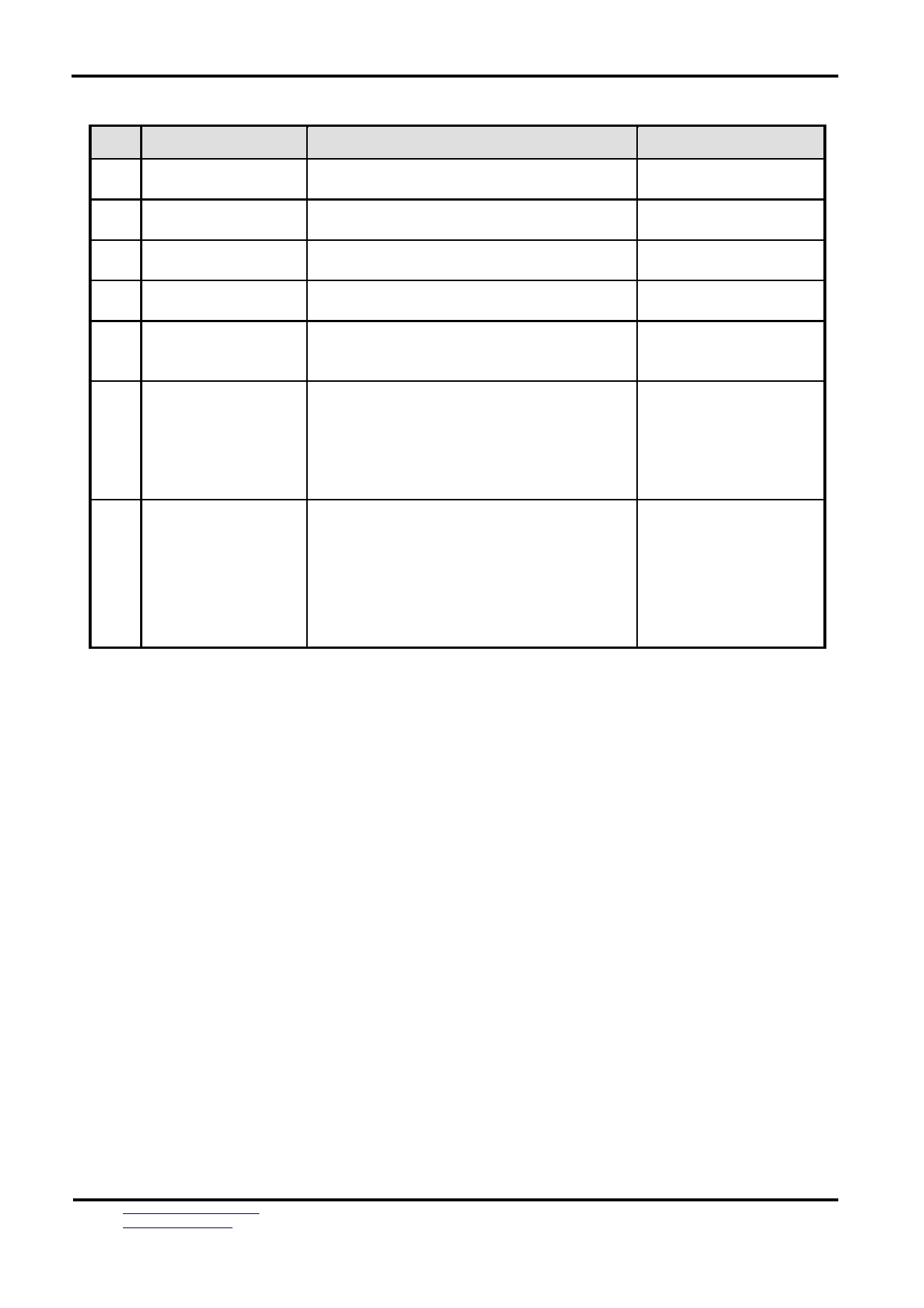
7
Environmental / Reliability Test
No
Test Item
Condition
Remarks
1
High Temperature
IEC60068-2-1:2007
Operation
Ta= +70 ℃ ,240hrs
GB/T 2423.2-2008
2
Low Temperature
IEC60068-2-1:2007
Operation
Ta= -20 ℃ ,240hrs
GB/T 2423.1-2008
3
High Temperature
IEC60068-2-1:2007
Storage
Ta = +80 ℃ ,240hrs
GB/T 2423.2-2008
Low Temperature
IEC60068-2-1:2007
4
Storage
Ta = -30 ℃ ,240 hrs
GB/T 2423.1-2008
Storage at High
5
Temperature and
Ta=+60 ℃ , 90% RH 240 hours
IEC60068-2-78 :2012
Humidity
GB/T 2423.3 — 2016
Start with cold
temperature,
End with high
6
Thermal Shock
-30 ℃ 30 min~+80 ℃ 30 min,
(non-operation)
Change time:5min,20 Cycles
temperature,
IEC60068-2-14:2009,
GB/T 2423.22-2012-Na
C=150pF , R=330 Ω, 5point/panel
Air :± 8kv , 5times ; Contact :
7
ESD
± 4kv , 5times ;
IEC61000-4-2:2001
GB/T 17626.2-2018
( Environment : 15 ℃ ~35 ℃, 30%~60% ,
86Kpa~106Kpa )
Note1: Ta is the ambi ent temperature of sample.
Note2: Before cosmetic and function test, the product must have enough recovery time, at least 24
hours at room temperature.
Note3: In the standard condition, there shall be no practical problem that may affect the display function.
After the reliability test, the product only guarantees operation, but don’t guarantee all of the cosmetic
specification.
URL:
Document Name:LMT101GNFWD-Manual-Rev1.0(w_dwg)
Page: 16 of 18
TOPWAY
LCD Module User Manual
LMT101GNMFWD
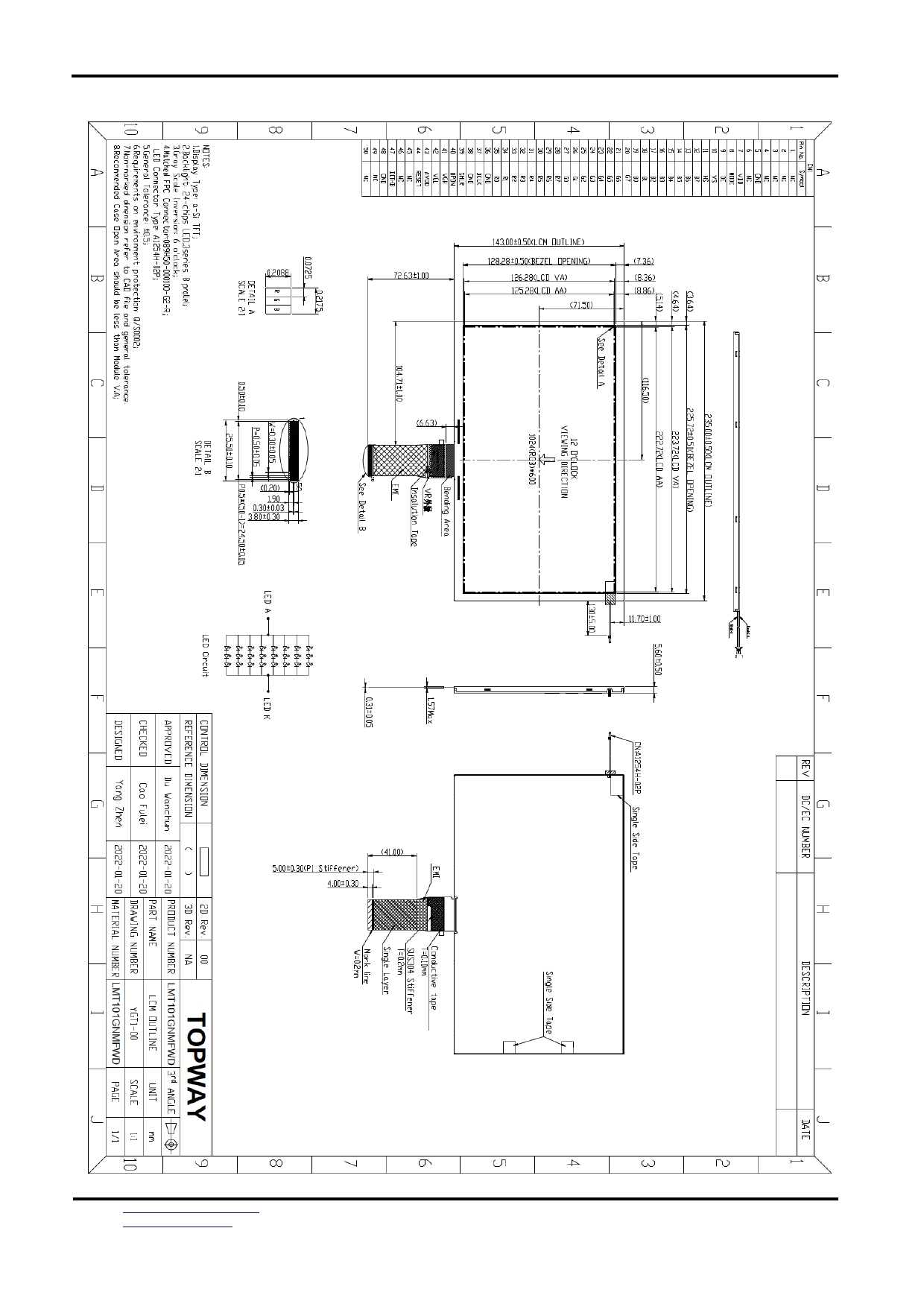
8
Mechanical Drawing
URL:
Document Name:LMT101GNFWD-Manual-Rev1.0(w_dwg)
Page: 17 of 18

TOPWAY
LCD Module User Manual
LMT101GNMFWD
9
Precautions for Use of LCD Modules
9.1
Handling Precautions
9.1.1
The display panel is made of glass. Do not subject it to a mechanical shock by dropping
it from a high place, etc.
9.1.2
If the display panel is damaged and the liquid crystal substance inside it leaks out, be
sure not to get any in your mouth, if the substance comes into contact with your skin or clothes,
promptly wash it off using soap and water.
9.1.3
Do not apply excessive force to the display surface or the adjoining areas since this may
cause the color tone to vary.
9.1.4
The polarizer covering the display surface of the LCD module is soft and easily scratched.
Handle this polarizer carefully.
9.1.5
If the display surface is contaminated, breathe on the surface and gently wipe it with a
soft dry cloth. If still not completely clear, moisten cloth with one of the following solvents:
— Isopropyl alcohol
— Ethyl alcohol
Solvents other than those mentioned above may damage the polarizer. Especially, do not use the
following:
— Water, Ketone ,Aromatic solvents
9.1.6
Do not attempt to disassemble the LCD Module.
9.1.7
If the logic circuit power is off, do not apply the input signals.
9.1.8
To prevent destruction of the elements by static electricity, be careful to maintain an
optimum work environment.
10.1.8.1
Be sure to ground the body when handling the LCD Modules.
10.1.8.2
Tools required for assembly, such as soldering irons, must be properly ground.
10.1.8.3
To reduce the amount of static electricity generated, do not conduct assembly and
other work under dry conditions.
10.1.8.4
The LCD Module is coated with a film to protect the display surface. Be care when
peeling off this protective film since static electricity may be generated.
9.2
Storage precautions
9.2.1 When storing the LCD modules, avoid exposure to direct sunlight or to the light of
fluorescent lamps.
9.2.2
The LCD modules should be stored under the storage temperature range. If the LCD
modules will be stored for a long time, the recommend condition is:
Temperature : 0 ℃ ~ 40 ℃ Relatively humidity: ≤ 80%
9.2.3
The LCD modules should be stored in the room without acid, alkali and harmful gas.
9.3
Transportation Precautions
9.3.1 The LCD modules should be no falling and violent shocking during transportation, and
also should avoid excessive press, water, damp and sunshine.
URL:
Document Name:LMT101GNFWD-Manual-Rev1.0(w_dwg)
Page: 18 of 18