
Model No.TM 150TDS50
MODEL NO. :
TM150TDS50
MODEL VERSION:
02
ISSUED DATE:
201 6 - 6 -8
VERSION
:
V1. 6
□ Preli m inary Specification
■ Final Product Specification
Customer :
Approved by
Notes
TIANMA Confirmed :
Prepar ed by
Checked by
Approved by
Rui Xu
Longping Deng
Feng Qin
This technical specification is subjected to change without notice
URL:topwaydisplay.com
Page 1 of 24

Model No.TM 150TDS50
Table o f Contents
Tableof Contents ............................................................................................................................................. 2
Record of Revision .......................................................................................................................................... 3
1 General Specifications ............................................................................................................................ 4
2 Input/Output Terminals. ........................................................................................................................... 5
3 Absolute Maximum Ratings .................................................................................................................... 7
4 Electrical Characteristics ........................................................................................................................ 8
5 Dispaly Colors And Input Data Information ........................................................................................ 1 1
6 Timing Chart ........................................................................................................................................... 13
7 Optical Characteristics..............................................................................................................15
8 Environmental / Reliability Test .................................................................................................18
9 Mechanical Drawing .............................................................................................................................. 19
10 Markings .................................................................................................................................................. 21
11 Packing TransportationAnd Delivery........................................................................................22
12 Precautions for Use of LCD Modules........................................................................................24
URL:www.topwaydisplay.com
Page 2 of 24
Model No.TM 150TDS50
Record o f Revision
Rev
Issued Date
Description
Editor
1.0
2012-05-03 Preliminary Release
Pean Wu
1.1
2012-08-03
Page 26, update back drawing, add tape position
on LED wire.
Pean Wu
1.2
2012-09-13
Page 19, correct product label "
TM150TDS50-XXX" to "TM150TDS50"
Pean Wu
1.3
2012-12-03 Page 9, modify VDD max from 12.6V to 13.2V
Rui Xu
1.4
2014-03-28 Modify the Power supply current on page 9
Fen He
1.5
2015-12-18
Add Model Versionon Page 1, add Viewing
Direction and Grayscale Inversion Direction
Rui Xu
1.6
2016-6-08 Update 2.1 PIN define of 19
Yujie.Luo
URL:www.topwaydisplay.com
Page 3 of 24

Model No.TM 150TDS50
1 General Specifications
Feature
Spec
Size
15 inch
Resolution
1024xRGBx768
Technology Type
a-Si
Pixel Configuration
RGB vertical stripe
Display Spec.
Pixel pitch(mm)
0.297(H) × 0.297(V)
Display Mode
TM with Normally White
Surface Treatment
Anti Glare
Viewing Direction
12:00
Gray Scale Inversion Direction
6:00
LCM (W x H x D) (mm)
326.5(H)×253.5 (V) ×11.8(D) (typ.)
Active Area(mm)
304.128(W) x 228.096 (V) (typ.)
With /Without TSP
Without TSP
Mechanical
CN1:DF14-20S-1.25C(HIROSE/connector)
Characteristics
Matching Connection Type
CN2:51146-0500(Molex/connector)
Weight (g)
1000g(typ.)
Backlight
LED backlight type
Replaceable lamp holder for backlight
Electrical
Interface
LVDS 1 port
C haracteristics
Color Depth
16.7M(6bit+ HiFRC)/262K
Note 1: Viewing direction for best image quality is different from TFT definition. There is a 180 degree
shift.
Note 2: Requirements on Environmental Protection: RoHS
Note 3: LCM weight tolerance: ± 5%
URL:www.topwaydisplay.com
Page 4 of 24
Model No.TM 150TDS50
2 Input/Output Terminals
2.1 LCD PINS
Matching connection type: DF14-20S-1.25C(HIROSE/connector)
Description
Pin No.
Symbol
Signal
Input data signal: 8bit
Input data
Remarks
MAP A
MAP B
signal:6bit
1
VCC
2
VCC
Power supply
Power supply
3
GND
4
GND
Ground
Ground
-
5
D0-
6
D0+
Pixel data
R2-R7,G2
R0-R5,G0
7
GND
Ground
Ground
-
8
D1-
9
D1+
Pixel data
G3-G7,B2-B3
G1-G5,B0-B1
10
GND
Ground
Ground
11
D2-
12
D2+
Pixel data
B4-B7,DE
B2-B5,DE
13
GND
Ground
Ground
14
CLK-
15
CLK+
Pixel clock
Pixel clock
16
GND
Ground
Ground
17
D3-
R0-R1,
R6-R7,
Pixel data
G0-G1,
G6-G7,
Ground
18
D3+
B0-B1
B6-B7
Selection of
19
MSL
LVDS Input data
High
Low or NC
High or Low
Note1
map
Selection of the
20
FRC
number of colors
Low
High or NC
CN1 socket(Module side): 185083-20121( P-TWO ELECTRIC TECHNOLOGY CO., LTD.)
URL:www.topwaydisplay.com
Page 5 of 24
Model No.TM 150TDS50
2.2 BACKLIGHT PINS
Matching connection type: 51146-0500(Molex/connector)
Pin
Symbol
Description
1
VDD
12V
2
GND
Ground
Back light ON/OFF control:
3
BRTC
5V-On / 0V-Off
4
PWM
PWM Luminance control
5
NC
NC
CN2: MSB24038P5(Producedby STM) or equivalent.
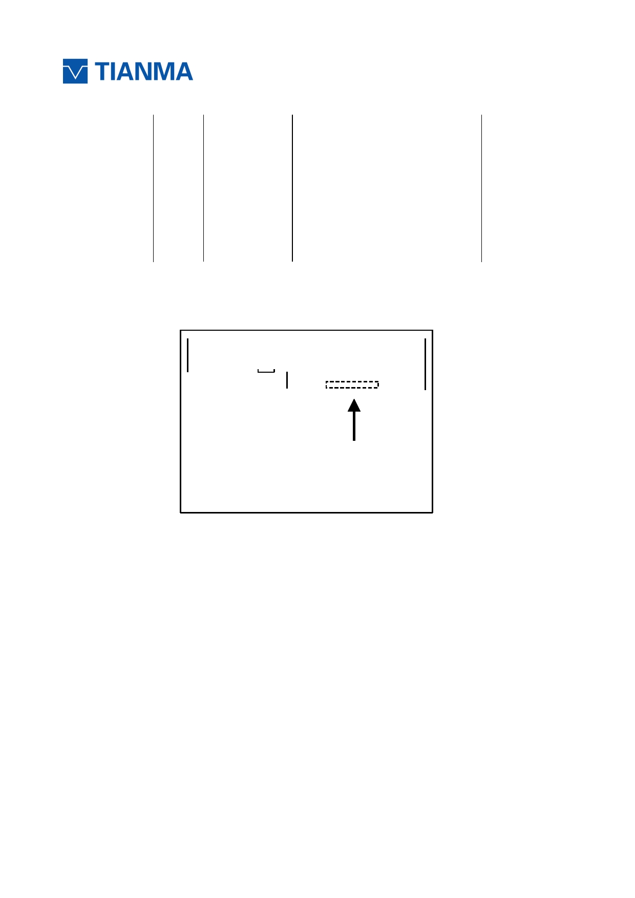
2.3 POSITIONS OF PLUG AND SOCKET
CN2
20 CN1
1
1
5
Insert direction
URL:www.topwaydisplay.com
Page 6 of 24
Model No.TM 150TDS50
3 Absolute Maximum Ratings
AGND=GND=0V, Ta = 25 ℃
Parameter
Symbol
Rating
Unit
Remarks
Power Supply Voltage
VCC
-0.3~+4.0
V
Ta = 25°C
Input voltage for signals
Vi
-0.3~+4.0
V
Ta = 25°C
Storage temperature
Tst
-30 ~ +80
°C
Note 1
Operating temperature
Top
-20 ~ +70
°C
Note 1, 2
Absolute humidity
AH
≤ 70
g/m 3
Ta > 50°C
Operating altitude
-
≤ 4,850
m
-20°C≤ Ta ≤ 70°C
Storage altitude
-
≤ 13,600
m
-30°C≤ Ta ≤ 80°C
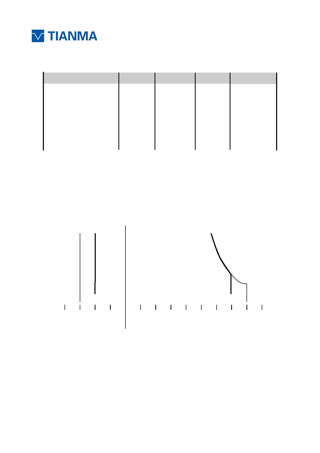
Note1: Temperatureand relative humidity range is shown in the figure below.
(a) 90%RH Max. (Ta ≤ 40°C)
(b) Wet-bulb temperature should be39°C Max. (Ta>40°C)
(c) No condensation.
Note2: The temperature of panel display surface area should be -20°C Min and 80°C Max.
Relative Humidity (% RH )
80
60
Operating Range
40
Temperature ( ℃ )
20
5
Storage Range
-40
-20
0
20
40
60
80
URL:www.topwaydisplay.com
Page 7 of 24
Model No.TM 150TDS50
4 Electrical Characteristics
4.1 Driving For LCD
AGND=GND= 0V , Ta = 25 ℃
Parameter
Symbol
min.
typ.
max.
Uni
t
Remarks
Power supply voltage
VCC
3.0
3.3
3.6
V
-
Power supply ripple
Vp-p
200
mV
Including
spike noise
Power supply current
ICC
-
500
550
mA
at VCC = 3.3V
Note 1
Permissible ripple voltage
VRP
-
-
100
mV
VCC
Differential input voltage
︱ Vid ︱
250
450
mV
Differential input
High
VTH
-
-
100
mV
threshold voltage for
VCM = 1.25V
LVDSreceiver
Low
VTL
-100
-
mV
Note2
Input voltage width for LVDS
receiver
Vi
0
-
1.90
V
-
Terminatingresistor
RT
-
100
-
Ω
-
Rush current
I rush
-
-
1.5
A
Note3
Input voltage for
High
VFH
2.0
VCC
V
MSL signals
Low
VFL
0
0.4
V
Note 1: All black pattern
Note 2: Common mode voltage for LVDSreceiver
Note 3: Measurement Conditions:
URL:www.topwaydisplay.com
Page 8 of 24
Model No.TM 150TDS50
4.2 Driving For Backlight
(Ta=25°C) Note1
Parameter
Symbol
min.
typ.
max.
Unit
Remarks
Power supply voltage
VDD
10.8
12.0
12.6
V
Power supply current
IDD
-
480
650
mA
Input voltage for
High
VDFH1
2.0
5.0
V
PWM signal
Low
VDFL1
0
0.4
V
Input voltage for
High
VDFH2
2.0
5.0
V
BRTC signal
Low
VDFL2
0
0.4
V
PWM frequency
fpwm
200
(20K)
Hz
PWM pulse width
tPWH
10
us
Led life time
Hr
50000
-
-
Hour
Note1
Note1: The led life time is defined as the time when it continues to operate under the conditions
at Ta = 25 ± 2 ℃ and Duty 100% until the brightness becomes ≤ 50% of its original
value. Operating LED under high temperature environment will reduce life time and lead
to color shift.
URL:www.topwaydisplay.com
Page 9 of 24
Model No.TM 150TDS50
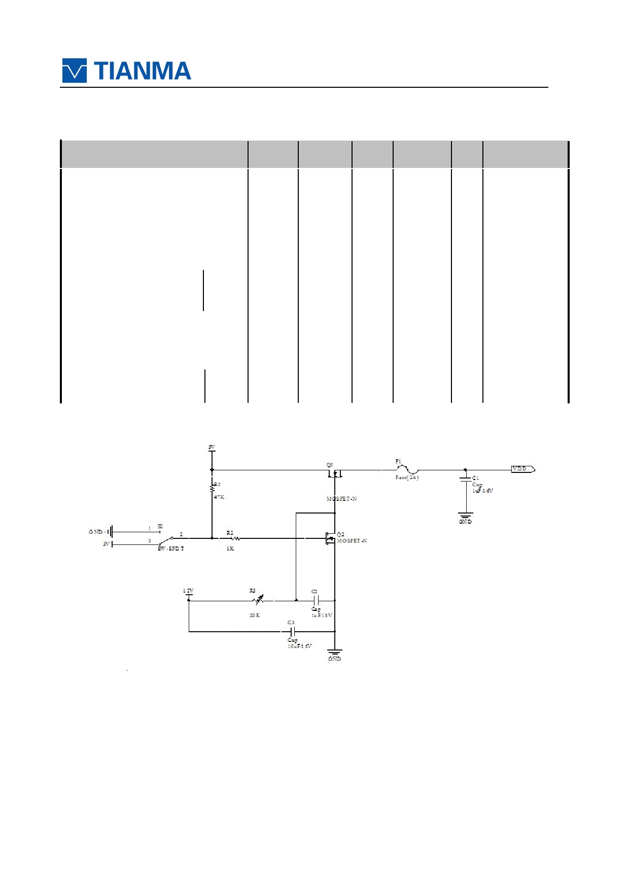
4.3 Block Diagram
Host
LCD module Product)
D0+
100 Ω
D0-
LCD panel
D1+
100 Ω
D1-
H: 1024 × 3 (R, G, B)
V: 768
D2+
100 Ω
D2-
D3+
100 Ω
D3-
CLK+
100 Ω
CLK-
DPS
FRC
768 lines
Power supply
for gradation
V-driver
GND
Note1
Note2
Fuse
DC/DC
VCC
converter
Fuse
VDD
PWM
LED driver
BRTC
LED Backlight
GND
LCD panel signal processing board
FG
Note1: Relations between GND (Signal ground and LED driver ground) and FG (Frame ground)
in the LCD module are as follows:
GND - FG
Connected
Note2: GND and FG must be connected to customer equipment’s ground, and it is
recommended that these grounds be connected together in customer equipment.
URL:www.topwaydisplay.com
Page 10 of 24
Model No.TM 150TDS50
5 DISPLAY COLORS AND INPUT DATA INFORMATION
5.1 DISPLAYCOLORS AND DATA SIGNAL
This product can display in equivalent to 16,777,216 colors in 256 scales.Also the relation
between display colors and input data signals is as the followingtable.And it can display in
equivalent to 262,144 colors in 64 scales, without data signals R7, R6, G7, G6, B7, B6 in the
following table.
Display
Data signal ( 0:Low level , 1:High Level )
colors
R7 R6 R5
R4 R3 R2 R1 R0
G7 G6 G5 G4 G3 G2 G1 G0
B7 B6 B5 B4 B3 B2 B1 B0
Black
0 0 0 0 0 0 0 0 0 0 0 0 0 0 0 0 0 0 0 0 0 0 0 0
Blue
0 0 0 0 0 0 0 0 0 0 0 0 0 0 0 0 1 1 1 1 1 1 1 1
Red
1 1 1 1 1 1 1 1 0 0 0 0 0 0 0 0 0 0 0 0 0 0 0 0
Magenta 1 1 1 1 1 1 1 1 0 0 0 0 0 0 0 0 1 1 1 1 1 1 1 1
Green
0 0 0 0 0 0 0 0 1 1 1 1 1 1 1 1 0 0 0 0 0 0 0 0
Cyan
0 0 0 0 0 0 0 0 1 1 1 1 1 1 1 1 1 1 1 1 1 1 1 1
Yellow
1 1 1 1 1 1 1 1 1 1 1 1 1 1 1 1 0 0 0 0 0 0 0 0
White
1 1 1 1 1 1 1 1 1 1 1 1 1 1 1 1 1 1 1 1 1 1 1 1
Black
0 0 0 0 0 0 0 0 0 0 0 0 0 0 0 0 0 0 0 0 0 0 0 0
Dark
0 0 0 0 0 0 0 1 0 0 0 0 0 0 0 0 0 0 0 0 0 0 0 0
0 0 0 0 0 0 1 0 0 0 0 0 0 0 0 0 0 0 0 0 0 0 0 0
:
:
:
Bright
1 1 1 1 1 1 0 1 0 0 0 0 0 0 0 0 0 0 0 0 0 0 0 0
Red
1 1 1 1 1 1 1 0 0 0 0 0 0 0 0 0 0 0 0 0 0 0 0 0
1 1 1 1 1 1 1 1 0 0 0 0 0 0 0 0 0 0 0 0 0 0 0 0
Black
0 0 0 0 0 0 0 0 0 0 0 0 0 0 0 0 0 0 0 0 0 0 0 0
Dark
0 0 0 0 0 0 0 0 0 0 0 0 0 0 0 1 0 0 0 0 0 0 0 0
0 0 0 0 0 0 0 0 0 0 0 0 0 0 1 0 0 0 0 0 0 0 0 0
:
:
:
Bright
0 0 0 0 0 0 0 0 1 1 1 1 1 1 0 1 0 0 0 0 0 0 0 0
Green
0 0 0 0 0 0 0 0 1 1 1 1 1 1 1 0 0 0 0 0 0 0 0 0
0 0 0 0 0 0 0 0 1 1 1 1 1 1 1 1 0 0 0 0 0 0 0 0
Black
0 0 0 0 0 0 0 0 0 0 0 0 0 0 0 0 0 0 0 0 0 0 0 0
Dark
0 0 0 0 0 0 0 0 0 0 0 0 0 0 0 0 0 0 0 0 0 0 0 1
0 0 0 0 0 0 0 0 0 0 0 0 0 0 0 0 0 0 0 0 0 0 1 0
:
:
:
0 0 0 0 0 0 0 0 0 0 0 0 0 0 0 0 1 1 1 1 1 1 0 1
Bright
Blue
0 0 0 0 0 0 0 0 0 0 0 0 0 0 0 0 1 1 1 1 1 1 1 0
0 0 0 0 0 0 0 0 0 0 0 0 0 0 0 0 1 1 1 1 1 1 1 1
URL:www.topwaydisplay.com
Page 11 of 24
Model No.TM 150TDS50
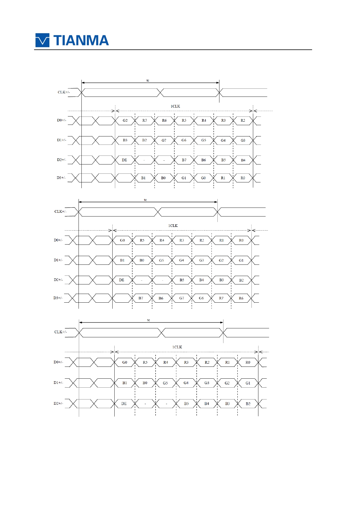
5.2 DATA MAP
(1) LVDS Input data signal: 8bit, MAP A (MSL: High, FRC: Low)
(2) LVDS Input data signal: 8bit, MAP B (MSL: Low or NC, FRC: Low)
(3) Input data signal: 6bit (MSL: High, FRC: High or NC)
URL:www.topwaydisplay.com
Page 12 of 24
Model No.TM 150TDS50
6 T iming Chart
6.1 TIMING CHARACTERISTICS
Parameter
Symbol min.
typ.
max.
Unit
Remarks
1/tc
50
65.0
81.25 MHz
Clock
Frequency
15.384ns
tc
20
15.4
12.31
ns
(typ.)
16.54
20.68
25.77
µs
48.36kHz
Horizonta
Cycle
th
(typ.)
l signals
1150
1344
1800
CLK
Display period
thd
1024
-
13.1
16.67
20
ms
Vertical
Cycle
tv
60.0Hz(typ.)
signals
776
806
1023
H
Display period
tvd
768
-
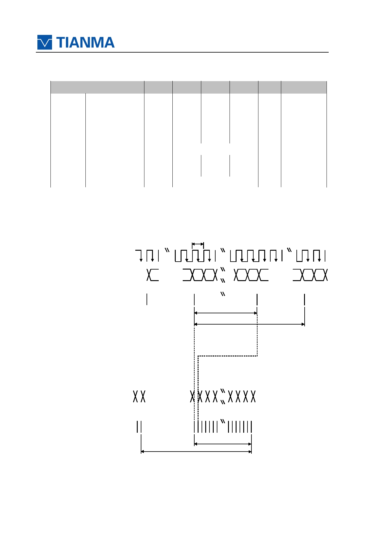
6.2 INPUT SIGNAL TIMING CHART
Horizontal timing
tc
CLK
DATA
(R0-R7)
INVALID
1
2
1023 1024
INVALID
(G0-G7)
(B0-B7)
DE
thd
th
Vertical timing
DATA
(R0-R7)
INVALID
INVALID
(G0-G7)
(B0-B7)
1 2
767 768
DE
tvd
tv
URL:www.topwaydisplay.com
Page 13 of 24
Model No.TM 150TDS50
6.3 PIXEL DATA ALIGNMENT OF DISPLAYIMAGE
The followingchartis the coordinatesof per pixel
D(1,1)
D(2,1)
D(3,1)
D(1024,1)
D(1,1)
D(1,2)
D(2,2)
D(3,2)
D(1024,2)
R
G
B
D(1,3)
D(2,3)
D(3,3)
D(1024,3)
D(1,768)
D(2,768)
D(3,768)
D(1024,768)
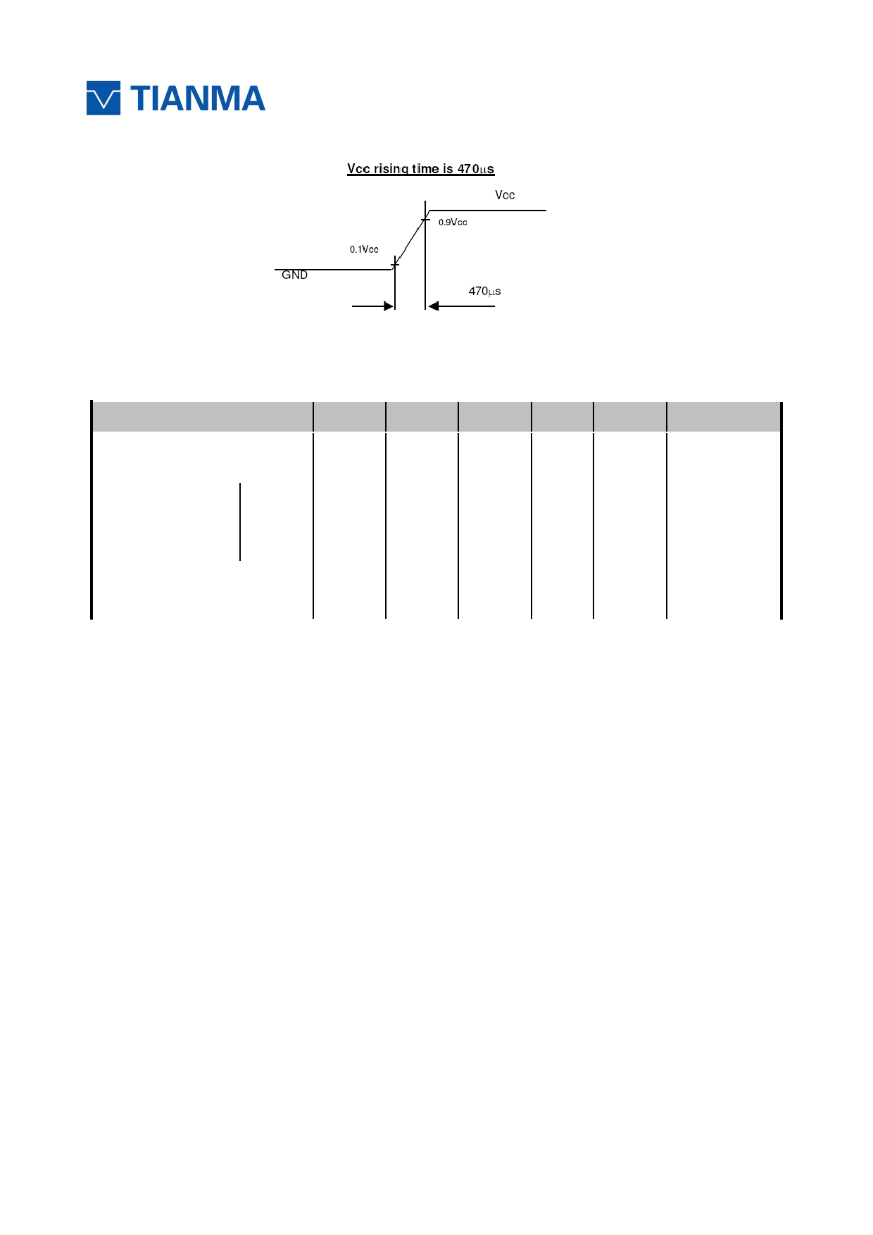
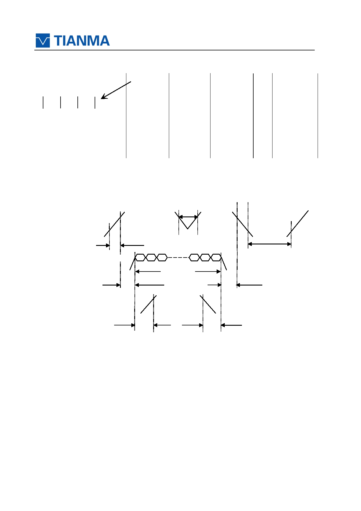
6.4 POWER SUPPLYVOLTAGESEQUENCE
6.4.1 The sequence of backlight and power
ON
t < 10ms *1
90%
VCC
3.0 V 90%
10%
2.5 V
0V
10%
10%
t1
90%
t4
90%
Display Signals
0V
VALID
t2
t3
90%
90%
Backlight signal
t5
t6
Timing Specifications:
t1 :0.5ms<t1 <10ms;
t2 :0.5 ms<t2 <50ms;
t3 :0ms<t3 <50ms;
t4 :t4 >1000ms;
t5 :t5 >200ms;
t6 :t6 >200ms;
URL:www.topwaydisplay.com
Page 14 of 24
Model No.TM 150TDS50
7 Optical C haracteristics
Item
Symbol Condition
Min
Typ .
Max
Unit
Remark
θT
70
80
-
θB
70
80
-
View Angles
CR ≧ 10
Degree Note 2
θL
70
80
-
θR
70
80
-
Note1
Contrast Ratio
CR
θ= 0 °
400
600
-
-
Note3
Luminance uniformity
U
-
1.25
1.33
-
Note6
T ON
Note1
Response Time
25 ℃
-
8
12
ms
T OFF
Note4
x
0.283
0.313
0.343
White
y
0.299
0.329
0.359
x
0.602
0.631
0.662
Red
y
Note5
Backlight is 0.325
0.355
0.385
Chromaticity
-
Note1
x
on
0.314
0.344
0.374
Green
y
0.578
0.608
0.638
x
0.123
0.153
0.183
Blue
y
0.057
0.087
0.117
NTSC
50
60
-
%
Note5
Luminance
L
350
400
-
cd/ ㎡ Note7
1: The values in upper table are only initial characteristics.
2: All measurement conditions are as follows.
Ta= 25 ° C, VDD= 3.3V,VCC=12V,100% brightness,
With typical timing characteristics.
Optical characteristics are measured after 30minutes light-on time in the dark room. Also
measurement method for luminance is as follows.
URL:www.topwaydisplay.com
Page 15 of 24
Model No.TM 150TDS50
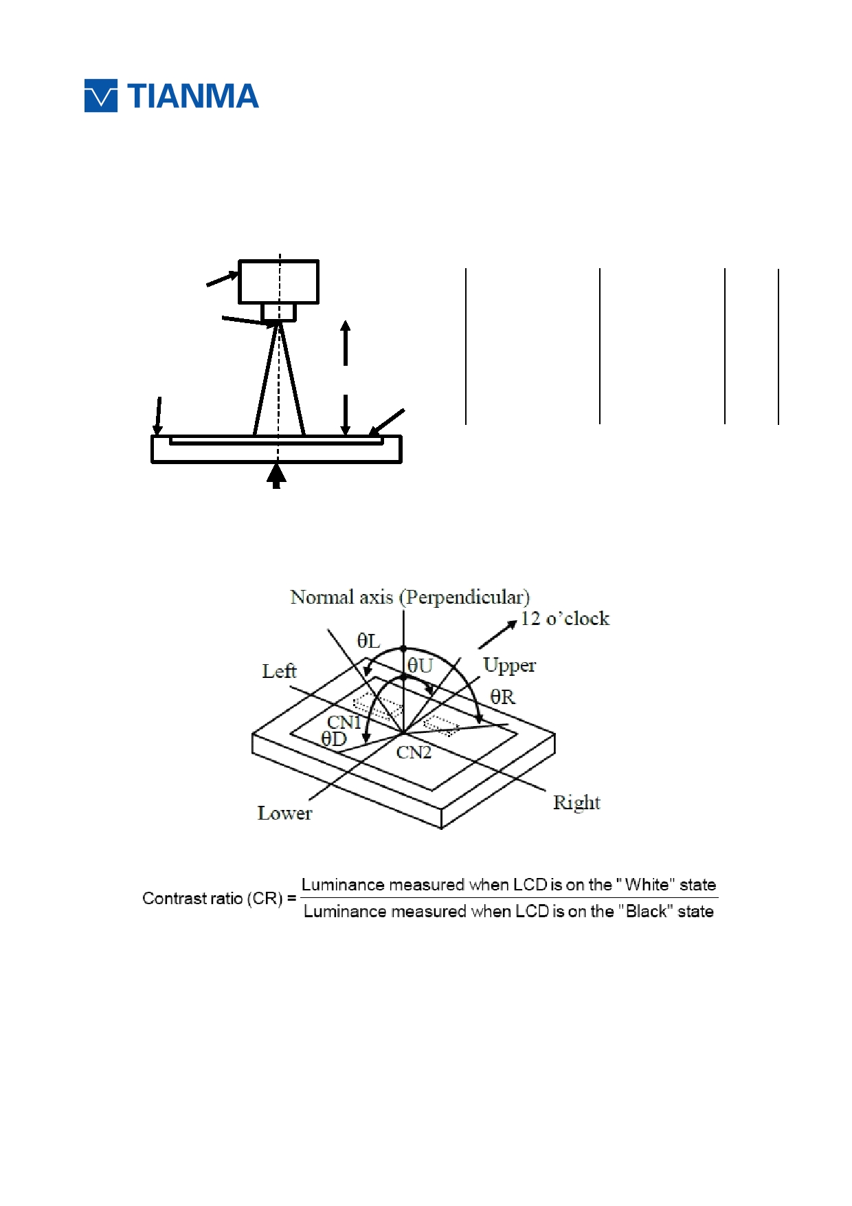
Note 1: Definition of optical measurement system.
The optical characteristics should be measured in dark room. After 5 Minutes operation, the optical
properties are measured at the center point of the LCD screen. All input terminals LCD panel must
be ground when measuring the center area of the panel.
Photo detector
Item
Photo detector Field
Contrast Ratio
Field
Luminance
SR-3A
1°
Chromaticity
500mm
TFT-LCD Module
Lum Uniformity
LCD Panel
Response Time
BM-7A
2°
The center of the screen
Note 2: Definition of viewing angle range and measurement system.
viewing angle is measured at the center point of the LCD by CONOSCOPE(ergo-80) 。
Note 3: Definition of contrast ratio
“White state “: The state is that the LCD should drive by Vwhite.
“Black state”: The state is that the LCD should drive by Vblack.
Vwhite: To be determined Vblack: To be determined.
URL:www.topwaydisplay.com
Page 16 of 24
Model No.TM 150TDS50
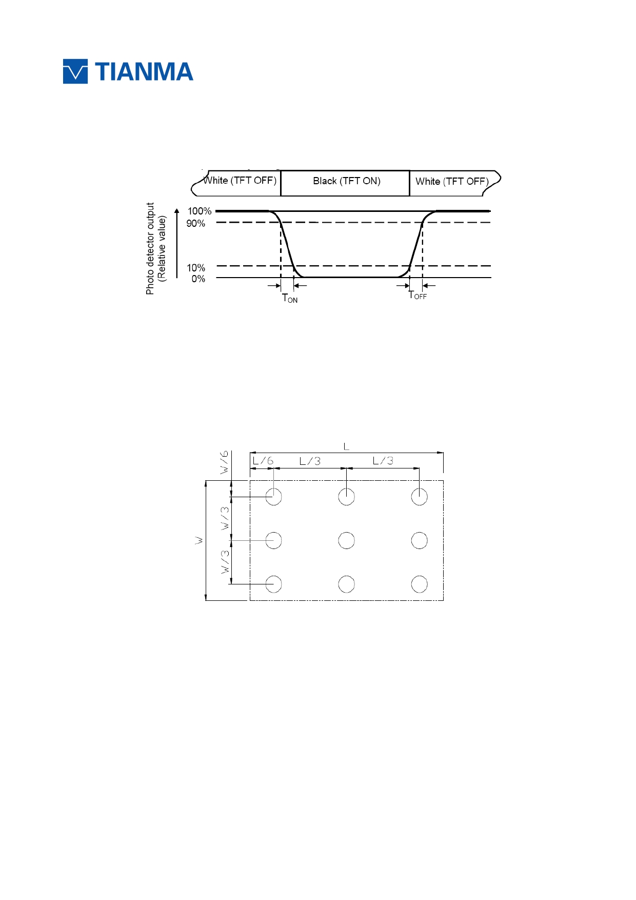
Note 4: Definition of Response time
The response time is defined as the LCD optical switching time interval between “White” state and
“Black” state. Rise time (T ON ) is the time between photo detector output intensity changed from 90%
to 10%. And fall time (T OFF ) is the time between photo detector output intensity changed from 10%
to 90%.
Note 5: Definition of color chromaticity (CIE1931)
Color coordinates measured at center point of LCD.
Note 6: Definition of Luminance Uniformity
Active area is divided into 9 measuring areas (Refer Fig. 2). Every measuring point is placed at the
center of each measuring area.
Luminance Uniformity (U) = Lmin/ Lmax
L-------Active area length W----- Active area width
Lmax: The measured Maximum luminance of all measurement position.
Lmin: The measured Minimum luminance of all measurement position.
Note 7: Definition of Luminance:
Measure the luminance of white state at center point.
URL:www.topwaydisplay.com
Page 17 of 24

Model No.TM 150TDS50
8 Environmental / Reliability T est
No
Test Item
Condition
Remarks
1
High Temperature
IEC60068-2-1:2007
Operation
Ts = +70 ℃ , 240 hours (Note1)
GB2423.2-2008
2
Low Temperature
IEC60068-2-1:2007
Operation
T a = -20 ℃ , 240 hours (Note1)
GB2423.1-2008
3
High Temperature
IEC60068-2-1:2007
Storage
Ta = +80 ℃ , 240 hours
GB2423.2-2008
4
Low Temperature
IEC60068-2-1:2007
Storage
Ta = -30 ℃ , 240 hours
GB2423.1-2008
Storage at High
5 Temperatureand
Ta = +50 ℃ , 80% RH max, 240hours
IEC60068-2-78 :2001
Humidity
GB/T2423.3—2006
Start with cold temperature,
6
Thermal Shock
-20 ℃ 30 min ~ +60 ℃ 30 min,
End with high temperature,
(non-operation)
Change time:5min, 100 Cycle
IEC60068-2-14:1984,
GB2423.22-2002
C=150pF,R=330Ω, 9point/panel
Air: ±15Kv,9points,25times/point;
7 ESD(Operation)
Contact: ±8Kv,9points,25times/point
IEC61000-4-2:2001
(Environment: 15 ℃ ~35 ℃ , 30%~60%.
GB/T17626.2-2006
86Kpa~106Kpa)
8 Package Drop Test
Height: 60cm,
IEC60068-2-32:1990
1corner, 3edges, 6surfaces
GB/T2423.8—1995
Frequency range:10~100Hz,11.76m/s ²
9
Vibration
1minute/cycle
IEC600682-6:1982
(Non-operation)
X,Y,Z directions
GB2423.10-1995
50times each directions
30G,11ms, ± X, Y ,Z directions,3times
IEC60068-2-27:1987
10
Shock
(Non-operation)
For each direction
GB/T2423.5 — 1995
Note1: Ts is the temperature of panel ’ s surface.
Note2: Ta is the ambient temperature of sample.
Note3: Before cosmetic and function test, the product must have enough recovery time, at least 2
hours at room temperature.
Note 4: In the standard condition, there shall be no practical problem that may affect the display
function. After the reliability test, the product only guarantees operation, but don’t guarantee all of the
cosmetic specification.
URL:www.topwaydisplay.com
Page 18 of 24
Model No.TM 150TDS50
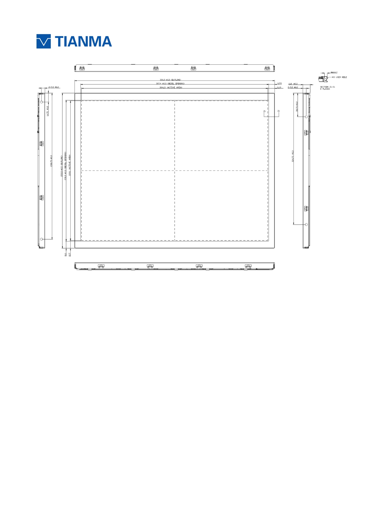
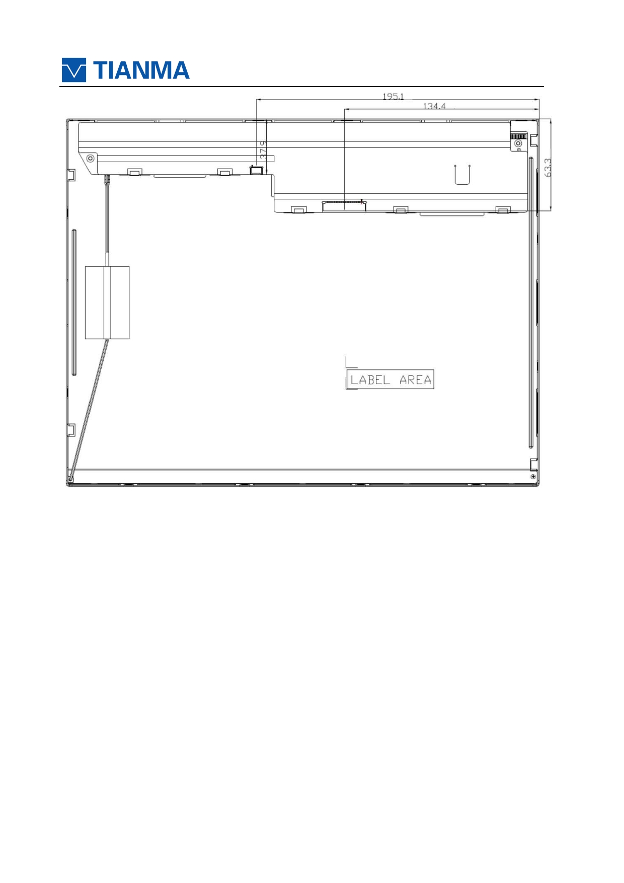
9 Mechanical Drawing
URL:www.topwaydisplay.com
Page 19 of 24
Model No.TM 150TDS50
URL:www.topwaydisplay.com
Page 20 of 24
Model No.TM 150TDS50
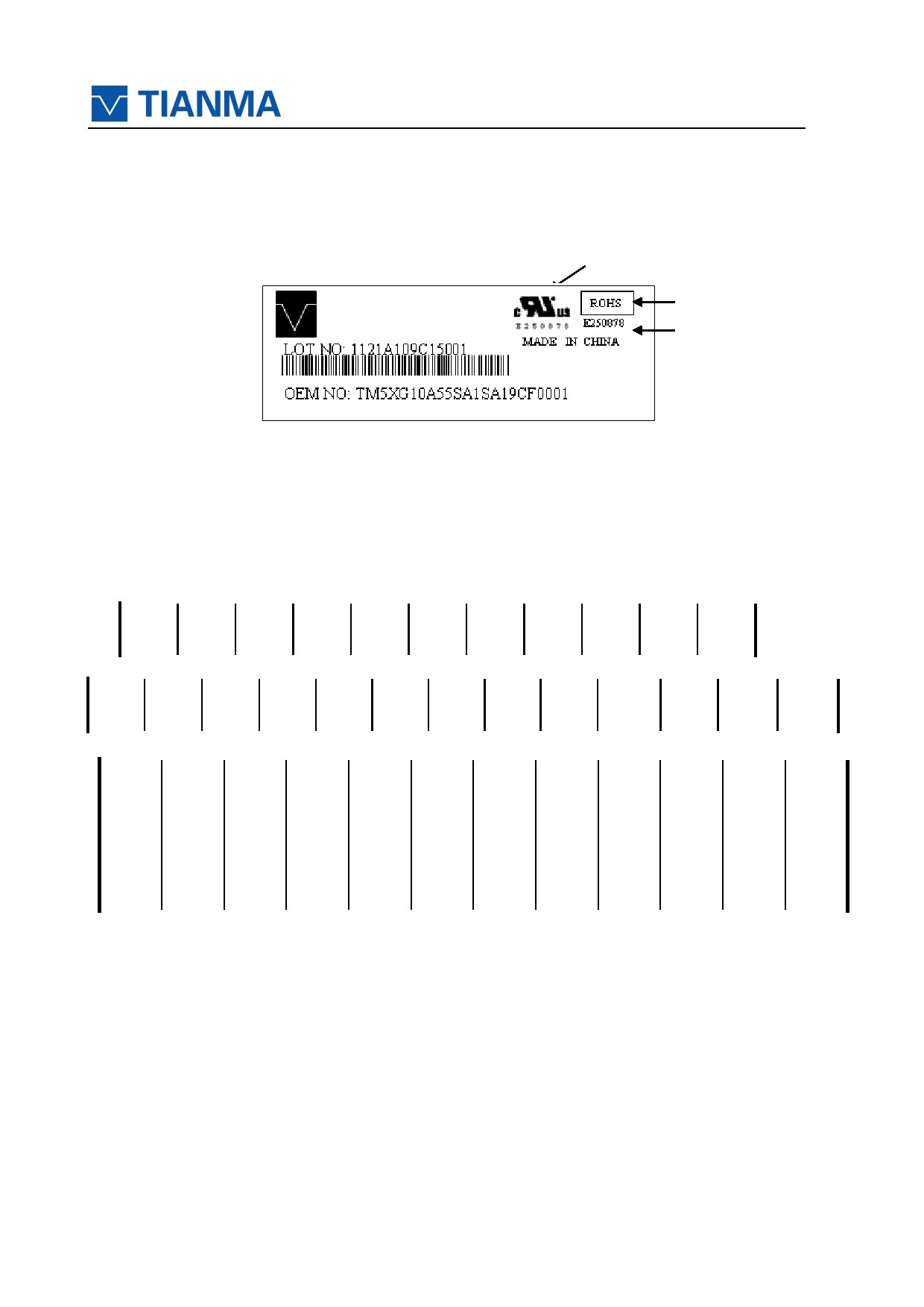
10 MARKINGS
The various markings are attached to this product. See “10.2 INDECATIONLOCATIONS” for
attachment positions.
10.1 PRODUCT LABEL
Product label
UL Mark
ROHS
TM150TDS50
Mark
Lot number
Country of
manufacture
OEM number
Note2
Note 1
Note1: The meaning of OEM number
TM5XG10A55SA1SA1
9CF
0001
AVIC internal code
Date code
S/N
Date code:
1st Character YearCodes
Month
2010
2011 2012
2013
2014
2015
2016
2017
2018 So on
Code
0
1
2
3
4
5
6
7
8
2nd Character Month Codes
Month January February March
April
May
June
July
August September October November December
Code
1
2
3
4
5
6
7
8
9
A
B
C
3rd Character Day Codes
Day
1st
2nd
3rd
4th
5th
6th
7th
8th
9th
10th
11st
Code
1
2
3
4
5
6
7
8
9
A
B
Day
12nd
13rd
14th
15th
16th
17th
18th
19th
20th
21st
22nd
Code
C
D
E
F
G
H
I
J
K
L
M
Day
23rd
24nd
25st
26nd
27rd
28th
29th
30th
31st
Code
N
O
P
Q
R
S
T
U
V
Note2: Do not attach anything such as label and so on, on the product label! In case repair the
product, AVICneeds the contents of product label such as the lot number, inspection date and so on,
to identify the warranty period with individual product. If AVICcannot decipher the contents of
product label, such repair shall be entitled to charge. Also AVICmay give a new lot number to
reconditioned products.
URL:www.topwaydisplay.com
Page 21 of 24
Model No.TM 150TDS50
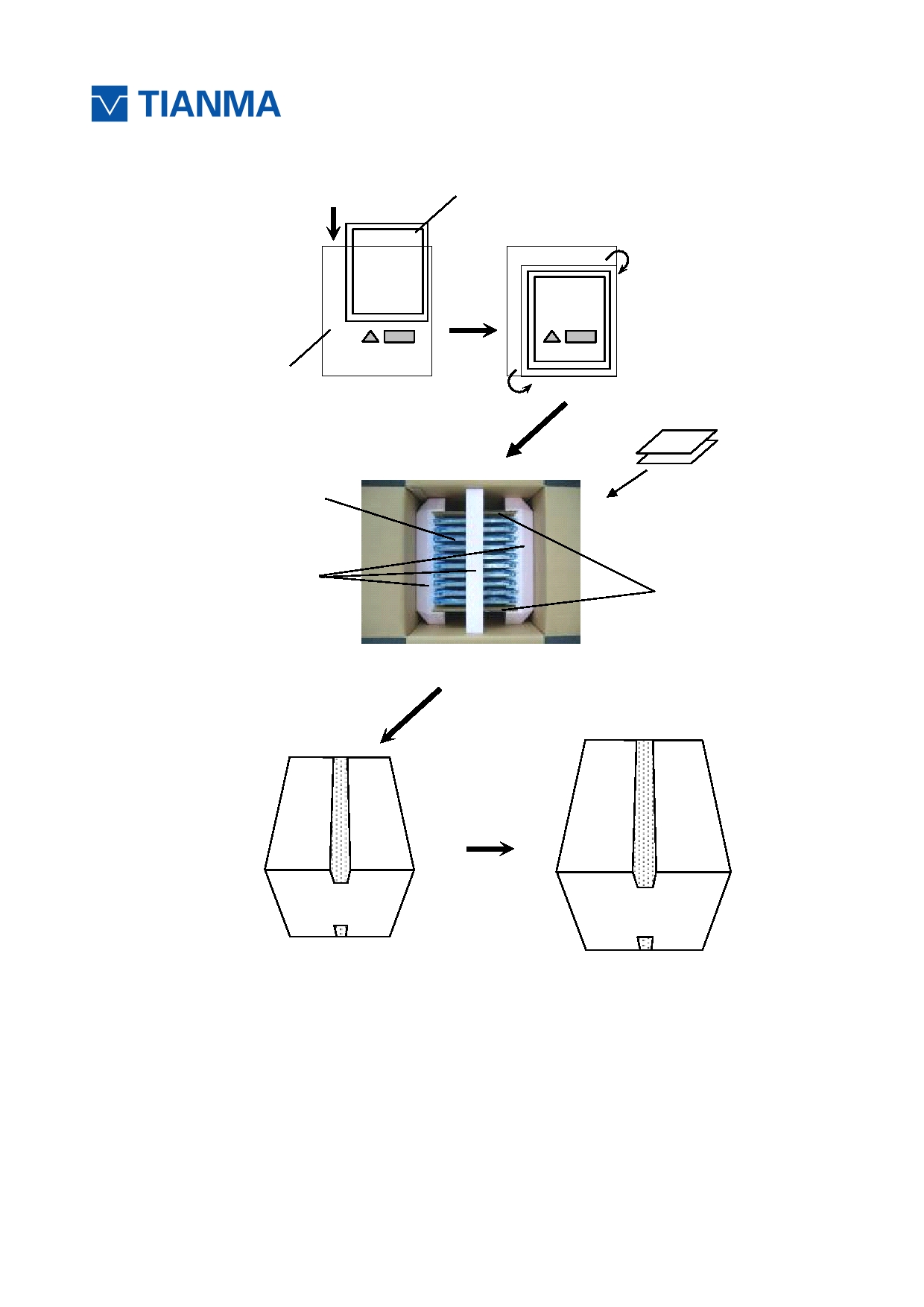
11 PACKING, TRANSPORTATION AND DELIVERY
Tianma will pack products to deliver to customer in accordance with Tianma packing
specifications, and will deliver products to customer in such a state that products will not suffer from
a damage during transportation .The delivery conditions are as follows.
1 1.1 PACKING
(1) Packing box
10 products are packed up with the maximum in a packing box (See “ 1 1.5 OUTLINE FIGURE
FOR PACKING“).
Products are put into a plastic bag for prevention of moisture with cushion, and then the bag is
sealed up with heat sealing.
The type name and quality are shown on outside of the packing box, either labeling or printing.
(2) Pallet Packing
① Packing boxes are tied on a cardboard pallet. (4 boxes×3 tiers maximum)
② Cardboard sleeve and top cap are attached to the packing boxes, and then they are fixed
by a band.
1 1.2 INSPECTION RECORD SHEET
Inspection record sheets are included in the packing box with delivery products to customer.It
is summarized to a number of products for pass/fail assessment.
1 1.3 TRANSPORTATION
The product is transported by vehicle, aircraft or shipment in the state of pallet packing.
1 1.4 Packing Material
No
Item
Model(Material)
Dimensions
Unit Weigt
(mm)
(Kg)
Quantity
Remark
1 LCM module
TM150TDS50
326.5x253.5x11.8
1.00
10
2 Partition broad Corrugated paper
357x235
0.05
2
3 Anti-static Bag
LD-PE
435x325x0.05
0.005
10
Anti-static
4 EPP1
EPP
422x340x79.5
0.197
2
5 EPP2
EPP
340x59x50
0.022
1
6 Carton-inside
Corrugated paper
378x343x430
1.15
1
7 Barcode Label
Paper
104x76
0.001
1
8 Total weight
11.7Kg ± 5%
URL:www.topwaydisplay.com
Page 22 of 24
Model No.TM 150TDS50
1 1.5 OUTLINE FIGURE FOR PACKING
LCD module
Antistatic pouch
Inspection record sheet
LCD
Export attention label
module
(Product)
Inner pad
Partition board
Inner packing box
Outer packing box
(Carton box)
(Carton box)
URL:www.topwaydisplay.com
Page 23 of 24

Model No.TM 150TDS50
12 Precautions for Use of LCD Modules
12.1
Handling Precautions
12.1.1 The display panel is made of glass. Do not subject it to a mechanical shock by
dropping it from a high place, etc.
12.1.2 If the display panel is damaged and the liquid crystal substance inside it leaks out, be
sure not to get any in your mouth, if the substance comes into contact with your skin or clothes,
promptly wash it off using soap and water.
12.1.3 Do not apply excessive force to the display surface or the adjoining areas since this
may cause the color tone to vary.
12.1.4 The polarizer covering the display surface of the LCD module is soft and easily
scratched. Handle this polarizer carefully.
12.1.5 If the display surface is contaMinated, breathe on the surface and gently wipe it with a
soft dry cloth. If still not completely clear, moisten cloth with one of the following solvents:
- Isopropyl alcohol
- Ethyl alcohol
Solvents other than those mentioned above may damage the polarizer. Especially,do not use the
following:
- Water
- Ketone
- Aromatic solvents
12.1.6 Do not attempt to disassemble the LCD Module.
12.1.7 If the logic circuit power is off, do not apply the input signals.
12.1.8 To prevent destruction of the elements by static electricity,be careful to maintain an
optimum work environment.
12.1.8.1 Be sure to ground the body when handling the LCD Modules.
12.1.8.2 Toolsrequired for assembly,such as soldering irons, must be properly ground.
12.1.8.3 To reduce the amount of static electricity generated, do not conduct assembly and
other work under dry conditions.
12.1.8.4 The LCD Module is coated with a film to protect the display surface. Be care when
peeling off this protective film since static electricity may be generated.
12.2 Storage precautions
12.2.1 When storing the LCD modules, avoid exposure to direct sunlight or to the light of
fluorescent lamps.
12.2.2 The LCD modules should be stored under the storage temperature range. If the LCD
modules will be stored for a long time, the recommend condition is:
Temperature: 0 ℃ ~ 40 ℃ Relatively humidity: ≤80%
12.2.3 The LCD modules should be stored in the room without acid, alkali and harmful gas.
12.3 Transportation Precautions
12.3.1 The LCD modules should be no falling and violent shocking during transportation,
and also should avoid excessive press, water, damp and sunshine.
URL:www.topwaydisplay.com
Page 24 of 24