TFT Display Buyer’s Guide: Picking the Right Interface (SPI, RGB, LVDS, MIPI)
1. The Crucial First Step: Understanding the Display Interface Landscape
1.1. Why LCD Interface Matters
When you’re choosing a display, it’s tempting to focus only on resolution or screen size. But the way your display connects to the processor — the interface — has just as much impact on your design. It affects everything from your PCB layout and pin usage, to power efficiency and overall performance. Pick the wrong one, and you might end up facing costly redesigns or a product that doesn’t perform the way you want.
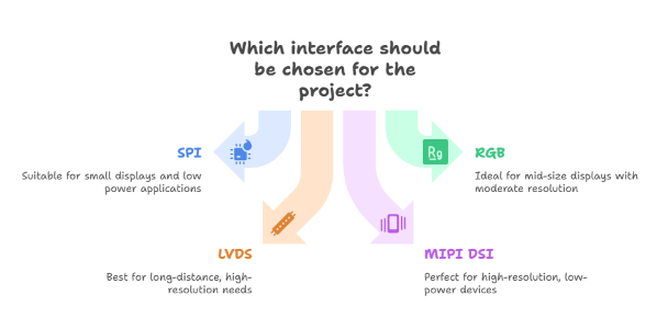
This guide breaks down the four most common interfaces — SPI, RGB, LVDS, and MIPI — so you can better match them to your project’s needs. Think of it as a practical roadmap for avoiding headaches and making smarter design decisions.
1.2. Foundational Concepts: A Primer for the Modern Engineer
Before diving into each interface, it helps to understand the players involved. A display system typically has:
- The host processor (your MCU or MPU)
- The display panel (LCD, OLED, etc.)
- The display driver IC (DDIC) — the “brains” that turn your processor’s commands into pixel-by-pixel control.
One of the most critical architectural decisions for a project is whether to use a display with a dedicated frame buffer. A frame buffer is a portion of random-access memory (RAM) that contains a bitmap of the image to be displayed on the screen. This concept is central to understanding the differences between "smart" and "dumb" display modules. In a "smart" display, the DDIC includes its own internal frame buffer, allowing the host processor to send image data or commands in bursts. Once the data is written to the display’s memory, the DDIC handles the continuous process of refreshing the screen on its own, freeing the host processor to perform other tasks. This is the underlying principle behind many serial interfaces like SPI.
In contrast, a "dumb" display lacks internal memory and requires the host processor to continuously stream pixel data in real-time. This "video mode" operation places a significant and constant load on the host processor and necessitates a high-bandwidth interface to avoid flickering or tearing. The most fundamental question a buyer must address is therefore not "Which interface should I choose?" but rather "Does my application require a display with or without a frame buffer?" This initial decision dictates the type of interface required, cascading into subsequent choices regarding the host processor, power budget, and overall system design. The choice of display interface is a direct function of the DDIC's architecture and the display's memory requirements, making this preliminary evaluation an essential first step.
2. The Workhorse: SPI (Serial Peripheral Interface)
2.1. Anatomy of a Synchronous Serial Bus
The Serial Peripheral Interface (SPI) is a de facto standard for synchronous serial communication, widely adopted in embedded systems for short-distance, inter-chip communication. It operates on a master-slave architecture, where a single master device—typically the host microcontroller—orchestrates communication with one or more slave devices, such as a display module. The interface is characterized by four primary signal lines:
- SCLK (Serial Clock): A clock signal driven by the master to synchronize data transfers.
- MOSI (Master Out Slave In): A data line that carries data from the master to the slave.
- MISO (Master In Slave Out): A data line that carries data from the slave back to the master.
- CS/SS (Chip Select / Slave Select): An active-low signal unique to each slave, which the master pulls low to enable communication with a specific device.
While a single master can communicate with multiple slaves, each slave requires its own dedicated CS pin from the master, which can become a limiting factor in designs with many peripheral devices. A key advantage of SPI is its support for full-duplex communication in its standard configuration, allowing data to be sent and received simultaneously.
In recent years, the standard SPI protocol has evolved with variants like Quad SPI (QSPI). While standard SPI uses a single data line for master-to-slave communication and another for the reverse, QSPI expands this to four data lines. This quadruples the data transfer speeds, making it particularly useful for high-speed communication with memory-intensive components like external flash memory, and it is now also being adopted by intelligent displays to provide enhanced performance.
2.2. Strengths, Limitations, and Ideal Applications
SPI's enduring popularity is rooted in its inherent simplicity and efficiency. Its low pin count, typically requiring only 4 to 6 pins, significantly simplifies board layout and reduces connector complexity, making it an excellent choice for space-constrained applications. Also, for prototyping and development, SPI is often a first choice for hobbyists and engineers due to its straightforward hardware setup and the widespread availability of software libraries for popular microcontrollers like Arduino and ESP32.
Pros:
- Very low pin count, great for compact designs.
- Simple wiring.
- Well-supported on popular MCUs like Arduino and ESP32.
Cons:
- Limited bandwidth.
- Not suitable for large or high-resolution displays.
- Software drivers can be tricky to set up despite simple hardware.
Where it fits best: Small character or graphic displays in IoT devices, wearables, and test equipment.
A common misconception is that the hardware simplicity of SPI translates to an easy-to-implement solution. While the electrical connections are indeed straightforward, the software implementation can be quite complex. As noted by some in the engineering community, getting even a basic SPI display configured and running can be non-trivial. This is because the process involves navigating intricate initialization sequences and porting specific driver components, which can be challenging without proper documentation or prior experience.4 Therefore, a buyer’s decision is not just a hardware choice; it is also a software-driven one. An interface that appears simple on paper may require a significant investment of time and expertise in driver development.
3. The Direct Link: Parallel RGB
3.1. The Raw, Unfiltered Signal
The Parallel RGB interface is a direct and raw method for transmitting image data to a display. It is a synchronous, parallel interface that requires a dedicated data line for each color bit, allowing for the simultaneous transmission of Red, Green, and Blue pixel data. In addition to the data lines, the parallel RGB interface requires several control signals to properly frame and synchronize the image:
- Pixel Clock (PCLK): A continuous clock signal that dictates when the display should capture the state of the parallel data lines.
- Horizontal Sync (HSYNC): A signal that marks the end of one horizontal line of pixels.
- Vertical Sync (VSYNC): A signal that marks the end of one full frame, or screen, of pixels.
- Data Enable (DE): A signal that indicates when valid pixel data is present on the data lines.
The precise timing and synchronization of these signals are critical for ensuring the image is displayed correctly, with specific inactivity periods, known as front and back porches, required before and after the sync pulses.
3.2. Frame Buffers vs. Video Mode: A Critical Distinction
Within the realm of parallel interfaces, there exists a crucial architectural distinction between MCU and RGB. This difference is directly tied to the presence of a frame buffer on the display module.
The MCU interface is designed for displays with an internal DDRAM, which acts as a frame buffer. In this "command mode" approach, the host processor sends data to the display's internal memory via a series of read, write, and chip-select signals. The display controller then handles the continuous task of refreshing the screen from its memory, freeing up the host processor for other tasks. This is an efficient approach for displaying static images or for interfaces that are updated in bursts.
In contrast, the Parallel RGB interface typically operates in a "video mode" and is used for displays that lack internal DDRAM. This is a raw, direct-drive interface where the host processor is responsible for continuously streaming pixel data to the display in real-time. This places a constant, high-speed demand on the host but simplifies the design and reduces the cost of the display module itself. This direct link is ideal for applications that require the continuous display of dynamic content, such as video.
3.3. Strengths, Limitations, and Use Cases
The primary advantage of the parallel RGB interface is its ability to support high data rates, making it an excellent choice for displaying high-color graphics and video on mid-to-high resolution displays.
Pros:
- Can handle high-color, mid-resolution graphics.
- Straightforward in terms of protocol.
- No packet parsing needed.
Cons:
- High pin count (16–24+), which complicates PCB layout.
- Very noisy (EMI issues) and limited to short cable runs.
Where it fits best: Mid-sized displays (4.3”–7”) in applications like industrial HMIs or consumer devices where pin count isn’t a dealbreaker.
4. LVDS: The Industrial Standard
4.1. Signal Integrity and High-Speed Transmission
LVDS (Low-Voltage Differential Signaling) was designed to solve the noise and pin-count problems of RGB. It serializes the data and sends it over differential pairs, which makes it fast, robust, and resistant to interference. It is critical to understand that LVDS is a physical layer specification only, not a communication protocol. This means it defines how a signal is transmitted electrically, but does not specify how the data is organized or what commands are sent.
4.2. Strengths, Limitations, and Use Cases
LVDS is a mature, well-established standard with a proven track record of reliability. Its key strengths include:
Pros:
- High Bandwidth: LVDS supports very high data rates, making it suitable for large, high-resolution displays.
- Excellent Noise Immunity: The differential signaling provides superior resistance to electromagnetic interference, ensuring stable performance in demanding industrial environments.
- Long Cable Distances: LVDS can transmit data reliably over much longer cable distances compared to other interfaces, with some applications supporting cables up to 10 meters. This flexibility is a significant advantage for designs where the host processor and display are physically separated.
- Reduced Pin Count: While not as low as MIPI, LVDS significantly reduces the number of required signal lines compared to parallel RGB for the same bandwidth.
Cons:
- Requires serializer/deserializer (SerDes) chips, adding cost and complexity.
- It’s a physical layer, not a full protocol, so designers must handle the higher-level data layer themselves.
Where it fits best: Large, high resolution displays in industrial PCs, medical imaging, and automotive systems — places where reliability is non-negotiable.
5. The Mobile Powerhouse: MIPI DSI
5.1. A Protocol for Modern Mobile Devices
MIPI DSI (Mobile Industry Processor Interface – Display Serial Interface) is the interface of choice for smartphones, tablets, and wearables. It uses packet-based communication over high-speed serial lanes, offering both efficiency and performance. A crucial distinction in the MIPI DSI protocol is the availability of two operating modes for sending data: Command Mode and Video Mode.
- Command Mode: This mode is used when the display has an internal frame buffer. The host processor sends commands and data in bursts using short packets, and the display's DDIC handles the continuous refresh from its internal memory. This is an extremely power-efficient approach that significantly reduces the host processor's workload, making it ideal for battery-powered devices.
- Video Mode: This mode is used for displays that do not have an internal frame buffer. The host processor continuously streams pixel data in real-time over the high-speed serial link, similar to parallel RGB but in a more efficient, serial format. While this places a higher demand on the host processor and consumes more power than Command Mode, it offers a cost-effective solution for high-resolution displays by eliminating the need for expensive on-display memory.
5.2. Strengths, Limitations, and Use Cases
MIPI DSI is the undisputed champion of modern high-performance, compact display applications. Its key advantages include:
Pros:
- Extremely high bandwidth (can drive 1080p, 4K+).
- Very power-efficient, perfect for battery devices.
- Low pin count with minimal EMI.
- Full protocol with bidirectional communication (can also handle touch input).
Cons:
- Complex to design and debug.
- Limited to short, board-to-board connections.
Where it fits best: Compact, high-performance devices like smartphones, tablets, wearables, and AR/VR headsets.
6. How to Choose: Key Factors to Weigh
Choosing the right display interface requires a careful evaluation of a project's unique requirements and constraints. There is no single "best" interface; only the most suitable one for a specific application.
- Resolution & Bandwidth Needs — High resolution video? You’ll need LVDS or MIPI.
- Pin Count & PCB Layout — Limited GPIOs? SPI or MIPI.
- Power Consumption — Battery-powered? MIPI or SPI.
- Signal Integrity & Distance — Long cables? LVDS.
- Cost & Complexity — RGB and SPI are simpler and cheaper; LVDS and MIPI cost more but deliver more.
6.1. Quick Comparison
The following table synthesizes the technical characteristics and application scenarios of each interface, providing a quick reference for engineers navigating the selection process.
| Interface | SPI | RGB | LVDS | MIPI DSI |
|---|---|---|---|---|
| Pin Count | 4-6 | 16-24 | 8-25 | 4-8+ |
| Typical Resolution | Up to 320x240 | Up to 800x480 | 1024x768+ | 1080P, 4K+ |
| Band Width | Low | Medium | High | Very high |
| Power Use | Low | High | Low | Very low |
| Cable Length | Very short | Very Short | Long (meters) | Very short |
| Use Cases | Small displays, IoT, Wearables | Mid-size display, HMIs | Industrial PCs, medical, automotive | Smartphones, tablets, VR/AR |
6.2. Common Pitfalls to Avoid
Beyond the technical specifications, a successful project requires careful planning to avoid common pitfalls.
- Ignoring future needs: Don’t just design for today’s resolution — plan for upgrades.
- Underestimating software effort: Even simple hardware interfaces can mean complex drivers.
- Poor PCB design: High-speed signals need careful layout to avoid noise issues.
7. Wrapping Up
There’s no one-size-fits-all interface. Each comes with strengths and trade-offs. For small, cost-sensitive devices, SPI is usually the answer. For mid-sized legacy systems, RGB can still be a solid option. For industrial or mission-critical applications, LVDS is the proven choice. And for modern, compact, high-performance devices, MIPI DSI leads the way.
At Topway, we’re here to help you navigate these decisions. Whether you need SPI for a simple IoT display or MIPI for the latest wearable tech, we’ll work with you to find the right fit for your project.