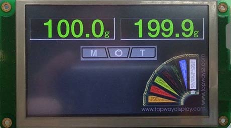
Build a digital scale display with smart TFT LCD
Background
The system we are going to build includes a data acquisition circuit with a host MCU and a HMT050ATA-2C smart LCD module as scale's display.
HMT050ATA-2C is a smart LCD module with following specifications:
- 5 inch TFT Color LCD with 800 (RGB) x 480 pixels with 16 bits color per pixel and LED backlight
- High-resolution resistive touch panel for user inputs and interactions
- 32 bits ARM Micro-Controller with a Smart LCD Engine to process graphics, commands from host
- A large flash memory to hold graphical data and configuration information locally
- A RS232 or a Logic-Level Serial Interface, connect the module to any host MCU or any other device supporting serial communication
- A USB interface to configure the module
The HMT050ATA-2C provides a very easy and fast way to create high-end embedded applications for Industrial Controls, Instruments, and Medical devices. The TFT LCD module shows user interface, which can be created with Topway's UI development tool. A host MCU may connect to the module, control it and receive input events.
Content
System Overview
A Digital scale is a very good example explaining the functionality and the way of developing applications with HMT050ATA-2C.
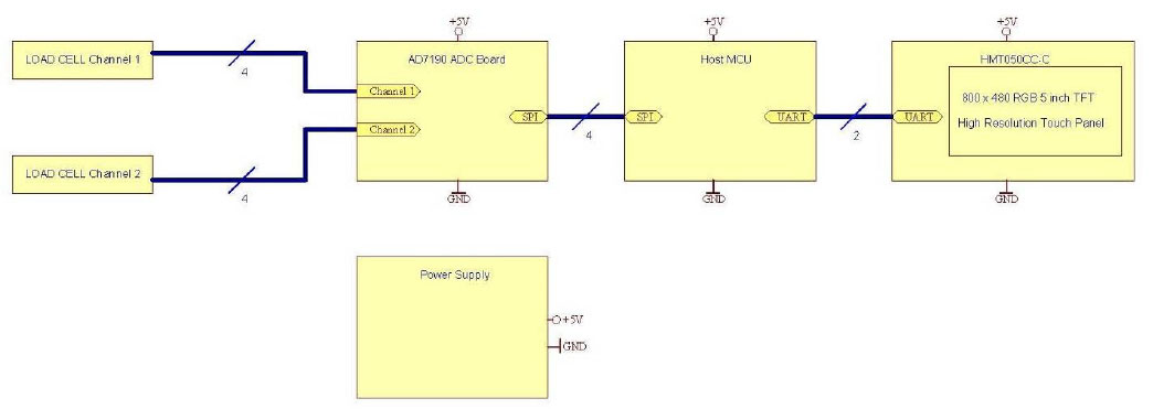
The proposed Digital Scale shall include:
- Two Load Cells
- ADC Board (e.g. based on AD7190) with SPI
- Host MCU Board (e.g. based on a small ARM Cortex M0, PIC or AVR) with SPI and UART
- Smart LCD Module HMT050CC-C with UART
- Power Supply
ADC Board is providing following functionality:
- Converting the bridge voltages of two load cell channels
- A ratio-metric measurement circuit is recommended
The Host MCU is providing following functionality:
- Setup and sampling of ADC values from the ADC Board
- Calculating the actual weights from the ADC values
- Transmitting the weight values as 32 Bit signed Values to the Smart LCD
- Checking some variables inside the Smart LCD and adjusting Modes of operation accordingly
- Recording Tare values in Tare Mode
The HMT050ATA-2C is providing following functionality
- Displaying different pages of contents depends on the operation mode of Host MCU
- Displaying weight values calculated inside the Host MCU
- Setting internal variables depends on Touch Panel events
The Host MCU also connects to the Smart LCD via a asynchronous serial interface in the following format:
- 8 Bit
- No Parity
- 1 Stop Bit.
Additionally, a flow control may be used by setting jumpers JP3 and JP4. Please refer to HMT050ATA-2C user manual for more details.
The Host MCU may use a baud rate of 9600 Bd or 115200 Bd. The baud rate can be selected on the
HMT050CC-C by using Jumpers JP1 and JP2:
- JP1 shorted / JP2 open select 115200 Bd
- JP2 shorted / JP1 open select 9600 Bd
The HMT050ATA-2C smart LCD module
Smart LCD module has the following parts and functions:
- Contents and functionalities are organized in one (or more) page(s)
- Page is a visual display on screen, contains:
- Images
- Icons
- Variables (VP)
- Animations
- Time and Date using internal Real Time Clock
- Page can hold multiple touch sensitive areas, which may trigger events like:
- Transition to another page
- Showing specific icons
- Setting variable value or performing calculation
- Sending touch event via serial interface
- Sounding internal buzzer
- Page may initialize variable (VP)
- User interaction or serial interface command can control smart lcd module transition from showing one page to another one
- The module includes a memory space, able to store global variables(VP), such as:
- Numeric value
- String
- Graph
- Bitmaps
- Through serial interface user can do:
- Switching between pages
- Text output
- Graphic operations like drawing line, rectangle and fill
- Reading and writing of variable
- Reading current page id
- Reading and updating internal real time clock
- Receiving touch event
- Setting backlight and buzzer
- Save values to internal flash storage
Development Plan
- Define scale's possible operation modes and functions
- Design a Data Acquisition Board with ADC and SPI interface (e.g. refer to AD7190 datasheet)
- Create a simple Host Interface Board with SPI connecting to the data acquisition board, and a serial
interface that can be used to communicate with HMT050ATA-2C - Create a design project with multiple pages using Topway UI Editor - RG Tools, which can create Graphical User Interface
and set internal variables (VP) to respond to user's interactions - Create communication software for the Host Board, which can sample ADC data, calculate weight and access the internal variables (VP) of HMT050ATA-2C
Continue reading this application note for the whole project.